11
En
Installation Procedure
8
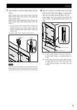
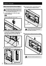
Locking the lock bar and fixing the lock
plate firmly in place with push rivet and
the anchor screw (M6 x 14mm) removed in
step 1 (2 locations: left and right sides).
If you cannot fix the push rivet in place from the side, fix
it in place from the bottom with the anchor screw (M6 x
14mm) (2 locations: left and right sides).
7
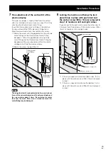
Fine adjustment of the vertical tilt of the
plasma display.
If the plasma display is slightly tilted from the vertical
after it is installed on the wall, you can adjust this tilt by
attaching the tilt adjustment metal fitting.
Insert the tilt adjustment metal fitting in the notch on
the top surface of the PDP side metal fitting that is
tilted downward and attach it by rotating the screw.
1
Rotate the screw until the gap between the wall side
metal fitting and the tilt adjustment metal fitting
disappears. When the gap between the wall side
metal fitting and the tilt adjustment metal fitting has
disappeared, the screw becomes difficult to rotate
and begins to lift up the plasma display.
2
Rotate the screw to adjust the tilt.
Gap
Screw head
Tilt adjustment
metal fitting
Tilt adjustment
metal fitting
Note
The range that the tilt can be adjusted by the screw is about
5 mm of the external dimension of the plasma display and
the screw rotates about 3 times. Be careful not to rotate
the screw too much. If the screw is turned too much, the
metal fitting may be damaged.
Plasma display
Lock the lock bar.
Anchor screw (*1)
Anchor screw (*2)
Unlocked
position
Locked
position
*1 If there are speakers installed on both sides, fix it in
place with the anchor screw (M6 x 14mm) removed
in step 1.
*2 If there is a speaker installed on the bottom, fix it in
place with the anchor screw (M6 x14mm) removed
in step 1.


