background image

100

INPUT 2

[Component, Horiz. 15.6 kHz x Vert. 50 Hz] (Note 1)
[Component, Horiz. 31.3 kHz x Vert. 50 Hz] (Note 1)
[Component, Horiz. 15.7 kHz x Vert. 60 Hz]
[Component, Horiz. 31.5 kHz x Vert. 60 Hz]

VIDEO Sig., Component
[Component, Horiz. 15.6 kHz x Vert. 50 Hz] (Note 1)
[Component, Horiz. 31.3 kHz x Vert. 50 Hz] (Note 1)
[Component, Horiz. 15.7 kHz x Vert. 60 Hz]
[Component, Horiz. 31.5 kHz x Vert. 60 Hz]
[Component, Horiz. 33.8 kHz x Vert. 60 Hz] (Note 2)
[Component, Horiz. 45.0 kHz x Vert. 60 Hz] (Note 2)

PC (Personal Computer) Sig.
[640 x 400, PC-9800 (56.4 Hz)]
[640 x 400, PC-9800, PC/AT compatibles (70.1 Hz)]
[640 x 480, PC-9800, PC/AT compatibles (59.9 Hz)]
[640 x 480, PC-9800, PC/AT compatibles (75 Hz)]
[800 x 600, PC-9800, PC/AT compatibles (60.3 Hz)]
[800 x 600, PC-9800, PC/AT compatibles (75 Hz)]
[1024 x 768, PC-9800, PC/AT compatibles (70.1 Hz)]
[1024 x 768, PC-9800, PC/AT compatibles (75 Hz), Macintosh (74.9 Hz)]
[1028 x 1024, PC-9800, PC/AT compatibles (60 Hz)]
[640 x 480, PC/AT compatibles (72.8 Hz)]
[800 x 600, PC/AT compatibles (56.3 Hz)]
[800 x 600, PC/AT compatibles (72.2 Hz)]
[1024 x 768, PC/AT compatibles (60 Hz)]
[1024 x 768, PC/AT compatibles (87 Hz) (Interlace)]
[640 x 480, Macintosh (66.7 Hz)]
[832 x 624, Macintosh (74.6 Hz)]
[1152 x 870, Macintosh (75.1 Hz)]

INPUT 3

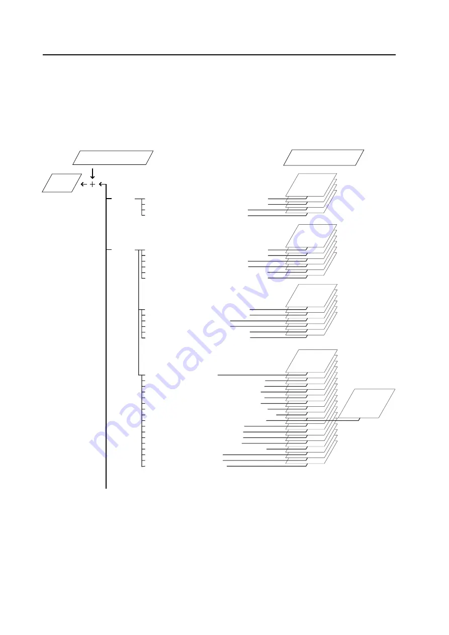
  Screen Adjustment Data for 
Use in Menu Mode

    Reproduce 
  Screen 
Data

  Screen Adjustment Data for 
Use in Integrator Mode

(Note 3)

• CLK FRQ

• H.POSI.

• V.POSI.

• CLK FRQ

• CLK FRQ

• H.POSI.

• V.POSI.

VIDEO Sig., RGB
[RGB, Horiz. 15.6 kHz x Vert. 50 Hz] (Note 1)
[RGB, Horiz. 31.3 kHz x Vert. 50 Hz] (Note 1)
[RGB, Horiz. 15.7 kHz x Vert. 60 Hz]
[RGB, Horiz. 31.5 kHz x Vert. 60 Hz]
[RGB, Horiz. 33.8 kHz x Vert. 60 Hz] (Note 2)
[RGB, Horiz. 45.0 kHz x Vert. 60 Hz] (Note 2)

• H.POSI.

• V.POSI.

• CLK PHS

• CLK FRQ

• H.POSI.

• V.POSI.

• CLK PHS

• CLK FRQ

• Data at 

<ZOOM> time

• H.POSI.

• V.POSI.

CONTINUED ON THE NEXT PAGE

Integrator Mode

5.4.6 SCREEN parameter memory area table

The memory area for SCREEN parameters has the following structure, and has no FACTORY area.

The SCREEN parameters are set to median values when performing INITIALIZE, for example.

The SCREEN parameters cannot be adjusted when selecting INPUT 1.

Note 1: EURO models only.

Note 2: U.S. models and TAIWAN models only.

Note 3: CLK PHS is effective both on the Menu and the Integrator mode at one time.

PC-9800

®

 is a registered trademark of NEC Corporation.

Macintosh

®

 is a registered trademark of Apple Computer Inc.

Содержание PDK-5001

Страница 1: ...a display and its dedicated mounting hardware Before installation and preparation work choose a safe and appropriate site after thorough consideration of construction materials used strength and surroundings If the adequate safeguards are not in place immediately halt the installation process and discontinue marketing activities TECHNICAL MANUAL Ver 1 1A About Mounting Installation The product is ...

Страница 2: ...001 38 4 3 1 Specifications 38 4 3 2 Assembling the stand 39 4 3 3 Mounting to the main unit 40 4 4 Plasma Display Ceiling Suspension Hardware one sided type PDK 5002 NOT AVALABLE IN USA 42 4 4 1 Specifications 42 4 4 2 Assembling and installing the mounting hardware and mounting the plasma display 44 4 5 Tiltable Plasma Display Wall Mount Hardware PDK 5006 NOT AVALABLE IN USA 48 4 5 1 Specificati...

Страница 3: ...Interface 104 5 5 3 List of RC 232C commands 105 5 5 4 About the GET commands 107 5 6 Combination Connection 108 5 6 1 Connections 108 5 6 2 Assigning IDs 110 5 7 KEY LOCK UNLOCK 113 5 7 1 Functions 113 5 7 2 How to switch KEY LOCK UNLOCK 113 OPERATING PRECAUTIONS AND RECOMMENDATIONS 114 6 1 About pseudo contour 114 6 2 Cautions 114 Maintenance and Cleaning 115 Table of Contents CAUTION To prevent...

Страница 4: ...weighs only 43 0 kg It can therefore be mounted at locations where conventional displays are difficult to install Supports a variety of signals from computers Full specification PC are supported in video modes from VGA 640 x 480 resolution to XGA 1024 x 762 resolution The SXGA 1280 x 1024 resolution mode also accommodates PC signals although a summary replay approach is employed in this mode The u...

Страница 5: ...5 Features ...

Страница 6: ...amp x 2 Bead band x 2 Operation manual x 1 Warranty card x 1 Light emitting panel 50 inch plasma display panel Aspect ratio 16 9 PEL 1280 x 768 XGA supported PEL pitch 0 858 H RGB trio x 0 808 V mm Gradation 256 16 77 million full colours Intensity 350 cd m2 white peak separate panel Viewing angle Horizontal more than 160 degrees Vertical more than 160 degrees Input output INPUT 1 Connector type s...

Страница 7: ...60 15 7 31 5 33 8 45 0 RGB Note 9 Component RGB Component RGB Component RGB Component Vertical Frequency Fv Hz Horizontal Frequency Fh kHz Signal Format 60 15 7 Model Name Dot x line Vertical Frequency Fv Hz Horizontal Frequency Fh kHz 31 5 31 5 37 9 37 5 35 2 37 9 48 1 46 9 48 4 56 5 60 35 5 Note 10 64 Note 10 35 49 7 60 2 68 7 Note 10 24 8 31 5 31 5 37 5 37 9 46 9 56 5 60 64 Note 10 70 1 59 9 72...

Страница 8: ...on manual x 1 Warranty card x 1 Light emitting panel 50 inch plasma display panel Aspect ratio 16 9 PEL 1280 x 768 XGA supported PEL pitch 0 858 H RGB trio x 0 808 V mm Gradation 256 16 77 million full colours Intensity 350 cd m2 white peak separate panel Viewing angle Horizontal 160 degrees or more Vertical 160 degrees or more Inputs outputs INPUT 1 Connector type NOTE 1 and NOTE 2 RCA jack compo...

Страница 9: ...e 9 Component RGB Component RGB Component RGB Component RGB Component RGB Component Vertical Frequency Fv Hz Horizontal Frequency Fh kHz Signal Format 50 60 15 6 15 7 Composite S video signal Model Name Dot x line Vertical Frequency Fv Hz Horizontal Frequency Fh kHz 31 5 31 5 37 9 37 5 35 2 37 9 48 1 46 9 48 4 56 5 60 35 5 Note 10 64 Note 10 35 49 7 60 2 68 7 Note 10 24 8 31 5 31 5 37 5 37 9 46 9 ...

Страница 10: ... satin gray paint Rear Laser satin gray paint For packaging information refer to 3 3 2 Unpacking Center of gravity Unit mm 609 1218 714 628 1108 357 Light sensor for the remote 98 5 65 5 1162 104 104 590 104 104 150 150 250 250 660 24 M8 ø16 mm with hole rivet Rear View 496 31 External Dimensions ...

Страница 11: ...11 Main Switch Main Unit Operation Panel Light Sensor for the Remote External Dimensions ...

Страница 12: ... ADJUST buttons Used to move the cursor on the menu screen or to increment decrement adjustment values 7 SET button Used to select an adjustment item in the menu screen or to change settings 8 KEY LOCK UNLOCK button hidden Renders the operation panel and remote operative or inoperative Connectors 9 AC INLET INPUT 3 Inputs These RGB inputs are composed of five BNC terminals 0 to They also support t...

Страница 13: ...e RCA jack and BNC terminal simultaneously since they are electrically connected to each other inside the body INPUT 1 Output Video Output terminal Signals fed to the INPUT 1 Video Input or are sent from this output terminal This terminal does not carry signals received at the S input terminal No signal is available at this output terminal when power is switched off or in standby status NOTE When ...

Страница 14: ...n or off standby Full Auto Zoom button Used to turn full auto zoom on or off Display button Used to view status of inputs or settings Adjustment buttons Used to move the cursor in the menu screen or to adjust various settings Input switches Used to select inputs Screen Size switch Used to select screen size Set button Used to select adjustment items in the menu screen or to change current settings...

Страница 15: ...15 Remote Control Unit ...

Страница 16: ...nts such as hang bolts 4 Sufficient work space Select a location with sufficient space for installation work The installation work should be conducted by more than two persons 5 Nearby equipment Air conditioning ducts or lamps located near the installation site may be subject to dust extreme temperatures humidity and condensation during installation Take suitable measures to protect them 6 Safe lo...

Страница 17: ...nsation occurs turn the unit off and leave it off for one hour or so It is also good practice to increase room temperature gradually 11 Power requirements This unit functions properly when powered at 10 of its rated voltage High impedance characteristics of lines at the installation site may distort the voltage output wave form effectively reducing voltage If any of the following occurs inspect th...

Страница 18: ...n of heat from the unit avoid blocking or covering any of these openings Fan 4 in number Air flow through the openings All four fans exhaust hot air from the unit All openings not assisted by fans serve as air inlets If the unit is hung from or embedded into a wall special operating temperature limits and other limitations may apply Refer to 3 4 Special Installation 96 5 35 75 Ø 5 10 345 70 45 54 ...

Страница 19: ...e beyond these limits may lead to nut failure Locations of useble mount holes are shown below Caps or plugs can be removed by turning them with a coin or another device Air outlet Fan Hole b Hole a in 6 locations Hole b in 18 locations Center line Hole b Hole b Hole b Center line Hole b Hole b Hole a Hole a Rear View Mounting Surface Mount hardware etc Hole a Hole b Bolt 10 to 23mm Installation Co...

Страница 20: ...l and vertical center lines as shown in the illustration below Do not secure the unit at four points arranged in a single row as shown below Methods for securing Unfavorable examples Methods for securing Favorable examples A Secured at eight points Installation Conditions B Secured at six points C Secured at four points with mounting hardware attached to the sides ...

Страница 21: ... be completely free of slack 2 Measure the clearance L between the strings at their point of intersection Distortion is expressed by Distortion L x 2 3 If L is found to be 0 pass the strings through the other bolt mount openings and repeat the measurements Any value of L greater than 0 indicates the presence of distortion If the measured values in both cases is 0 the distortion is negligible Mount...

Страница 22: ...ngs and instructions found on the upper surface of the carton 5 The front of the display is glass bearing Always take precautions to prevent sharp objects from striking this side 3 3 2 Unpacking 1 Package specifications 1382 W x 888 H x 454 D 58 0 kg 1 Ref No Terms 1 Upper face of the carton 2 Carton cover 3 Side carton 4 Lower face of the carton 5 Upper pad L 6 Upper pad C 7 Upper pad R 8 Under p...

Страница 23: ...on and pads may be used as a temporary stand for the unit Connections to and from the unit can be made after the side rear and front cartons are removed At this point the power switch and remote control may also be operated but this installation should be regarded as temporary Always secure the unit to the mounting hardware after pre installation wiring and adjustments are complete Never attempt t...

Страница 24: ...es for computer signals since these signals are more likely to degrade 5C 2V cables for example for 15 meter lengths Generally thicker cables will produce more reli able connections You can also improve signal quality by minimizing cable length Video cables plugged into video inputs and outputs close to dimmers neon signs air conditioning units or cables for wired broadcasts may occasionally deliv...

Страница 25: ...ndled cables can be drawn to the left or right Depending on specific requirements you may use the four openings indicated by solid circles How to unlock the speed clamp Use a pair of pliers to twist the clamp by at least a quarter turn and pull outward Remember that this procedure entails risk of damaging the clamp Display viewed from the rear Fasten cables using the supplied speed clamps Remember...

Страница 26: ... and obstructions 2 Any unit deformation warping occurring as a result of installation should be less than 1 mm 3 Never block or cover openings aside from those shown as blocked on the page to the right 4 The fittings should have a thickness of less than 20 mm This limit does not apply to fittings in examples 2 and 4 in the page to the right 5 L shaped fittings should have a thickness of less than...

Страница 27: ...27 Special Installation Mounting to fitting Example 1 Example 3 Never block this opening Examples of Mounting to Fittings Example 2 Example 4 Less than 35 mm Less than 35 mm ...

Страница 28: ... mounting hardware 88mm Special Installation Hanging from wall Operating Temperature Restrictions Ambient temperature regardless of clearance A 0 to 40 C or 0 to 35 C when the PDP S02 LR speaker system is installed Operating Temperature Restrictions for Upside down Installations Ambient temperature regardless of clearance A 0 to 30 C NOTE Different temperature restrictions apply to the PDK 5006 Re...

Страница 29: ...ck that the thickness and height of the fittings and the number of fixing bolts is correct Also refer to 3 4 1 Mounting to Fittings Heated air is exhausted from the interior of the unit by fans Before installation consider the heat nesistance of the wall or other surfaces behind the unit Exhaust temperatures can be 30 C C higher than the outside temperature For wall mounting bundle the cables so t...

Страница 30: ... in walls with space provided behind the unit Special Installation Embedding in the wall A B A B A B A B X Front of the unit Y Rear of the unit Viewed from Above Viewed from the Right Side Operating Temperature Restrictions Temperatures in space X and Y A No restrictions B 0 to 170 mm 0 to 40 C A No restrictions B 170 to 370 mm 0 to 35 C Operating Temperature Restrictions for Upside down Installat...

Страница 31: ...d height of the fittings and the number of fixing bolts is correct Also refer to 3 4 1 Mounting to Fittings Special Installation Embedding in the wall Temperature Measurement Points Informative Make measurements at a distance 5 cm from the unit without directly subjecting the thermometer to fan exhaust For spaces where temperature fluctuations are likely gather additional measurement points for an...

Страница 32: ... conditions must be met A mm B mm Ensure proper ventilation in space Y indicated in the illustration with an air conditioner or fan to prevent heated air from stagnating Observe the temperature restrictions specified below If heated air stagnates inside the area temperatures at points may rise high enough to produce breakdowns or fire Confirm that the inner walls are capable of resisting heat and ...

Страница 33: ...blocking or covering areas aside from those indicated by The method indicated with cross hatching should be avoided Before attaching the unit to fittings double check that the thickness and height of the fittings and the number of fixing bolts is correct Also refer to 3 4 1 Mounting to Fittings More than 700 mm More than 700 mm ...

Страница 34: ...Wires Bracket C D When suspending from a ceiling use the brackets shown at right to prevent concentrating loads on the upper two fixing points For additional safety secure the wires to separate fittings or parts of the ceiling Use mount screws composed of material stronger than soft steel and use hexagonal bolts Use wires adequate for the combined weight of the unit 43 0 kg and the weight of the s...

Страница 35: ...icated by The method indicated with cross hatching should be avoided Before attaching the unit to fittings double check that the thickness and height of the fittings and the number of fixing bolts is correct Also refer to 3 4 1 Mounting to Fittings Special Installation Ceiling suspension with wires More than 700 mm More than 700 mm ...

Страница 36: ...nting components permitting display panning over a range of 45 degrees and up to 25 degree downward tilting from horizontal Mount depth is less than 170 mm in vertical position without optional speaker This hardware enables installation of the unit in a wide range of locations Tiltable wall suspended hardware PDK 5006 Permits tilting of the display downward from horizontal by up to 25 degrees Moun...

Страница 37: ...allation work is complete Even if the particulars of an installation happen to be letter perfect your work may be perceived as inadequate unless you are patient and thorough in providing these precautions The following are highly dangerous and must be avoided at all times Any sudden application of force including pushing or pulling Splashing water on the unit Placing any object on the unit Touchin...

Страница 38: ...re plasma display Finish Paint Package dimensions 726 W x 425 D x 100 H mm Package weight 6 6 kg Accessories Base x 1 Stand pipe L x 1 Stand pipe R x 1 Vertical pipe x 1 Screw 4 x 12 x 6 Bolt M6 x 40 x 2 Cap x 2 Hexagonal wrench x 1 Flat washer x 4 Mount bolt M8 x 300 x 4 Turning over protective bolt x 2 Operating instractions x 1 Table top Stand PDK 5001 ...

Страница 39: ... Tighten the central screws first Stand pipe L 7 Assembly procedure 2 1 Align the vertical pipe with openings in the left and right stand pipes 2 Tighten bolts with the supplied hexagonal wrench to secure the vertical pipe 3 Insert caps into openings in the left and right stand pipes Screw 4 x 12 Screw 4 x 12 Stand pipe R Insert the pipe so the larger openings face outward Base Vertical pipe Hole ...

Страница 40: ...east two other persons when mounting the display Bolt number required four Washer number required four Hole rivet number required four Stand Sheet Step 3 After mounting the stand to the display fas ten the assembly to the floor to prevent it from turning over Fastening to the floor Fasten the assembly to the floor using appropriate commercially available screws Fasten the assembly to the floor usi...

Страница 41: ...nal drawings with display PDP 501MX PDP V501X Unit mm 150 1218 400 37 7 Mount locations for securing to floor screws Secure the assembly to the floor using M6 screws at least 20 mm long 108 292 152 533 258 765 700 469 558 656 6 325 130 7 27 ...

Страница 42: ... head bolt M5 x 16 x 1 Hexagonal socket head bolt M6 x 10 x 1 Hexagonal socket head bolt M6 x 30 x 1 Hexagonal socket head bolt M8 x 75 x 2 Hexagonal socket head bolt M10 x 85 x 2 Flat washer ø8 x 2 Flat washer ø10 x 2 Spring washer ø8 x 2 Spring washer ø10 x 2 Hole cover x 1 Spacer x 1 Pattern x 1 Operating instractions x 1 Mount contractor contact form x 1 The appropriate types of screws and oth...

Страница 43: ...ut a vertical axis after having been tilted sideways by 25 Without optional sperker Maximum sideways tilt 45 256 102 51 118 7 14 806 1162 325 170 ø240 5 ø70 External dimensions THIS ITEM IS NOT AVAILABLE PLEASE CONTACT PIONEER FOR INFORMATION 2 5 This circle shows the path that the outermost part of the plasma display follows when it is rotated about a vertical axis after having been tilted sidewa...

Страница 44: ...ket head bolt M5 x 16 3 Select the installation site then apply the supplied pattern to the ceiling drill the suitable holes and mount the ceiling flange COMP The appropriate types of screws and other display mounting components will depend on the strength and composition of the particular ceiling 4 Insert the post COMP into the ceiling flange COMP and secure the two with two hexagonal socket head...

Страница 45: ...ket head bolt M10 x 85 SME100H850FZK Hexagonal socket head bolt M8 x 75 SME80H750FZK Spring washer WS80FZK Flat washer WC80FZK Hexagonal socket head bolt for tilt angle adjustment M6 x 10 SME60H100FZK Monitor frame Cable hole Spacer Post COMP Center rod Monitor bracket Hole cover Used to hide holes drilled in the ceiling Hexagonal socket head bolt M5 x 16 SME50H160FZK THIS ITEM IS NOT AVAILABLE PL...

Страница 46: ...rizontal Determine the desired angle then retighten the upper mount screws for both the left and right monitor brackets Holes in the monitor brackets serve as angle marks in 5 degree increments 7 Adjust the left and right rotational angle of the plasma display panning over a range of 45 degrees on each side Hold the monitor frame and rotate the display to the desired angle then secure the display ...

Страница 47: ...47 THIS PAGE IS INTENTIONALLY BLANK ...

Страница 48: ...r Finish Laser satin gray paint on front semi matte black paint on rear Accessories Vertical frame left and right x 2 Horizontal frame x 2 Hexagonal socket head flange bolt x 8 Monitor mount bolt with washer x 8 Washer x 4 Hexagonal wrench x 1 Operating Temperature Restrictions Ambient temperature 0 to 40 C Operating Temperature Restrictions for Upside down Installations Upside down installation i...

Страница 49: ...SE CONTACT PIONEER FOR INFORMATION 49 THIS ITEM IS NOT AVAILABLE PLEASE CONTACT PIONEER FOR INFORMATION 25 390 125 1 38 36 6 589 400 20 32 6 6 39 6 32 40 40 714 1218 1194 910 455 355 555 655 810 14 ø 21 23 x ø 35 14 ø ø 23 1162 1214 ...

Страница 50: ...arate one end of the hook from the screw 2 Hold the upper part of the vertical frame and open to an approximate width of 10 cm 3 Mount the horizontal frame to the vertical frames a Loosen the screw until you can no longer see its end through this opening a This surface should face the wall This side should face the wall The smaller holes should face the wall Hexagonal wrench Positioning the screw ...

Страница 51: ...priate for the wall s strength and composition The nuts of the monitor fastening bolts should be tightened so that their surface is level with the screw CAUTION b b b b 3 Mounting monitor fastening bolts to the plasma display 1 Mount the monitor fastening bolts to the four rear corners of the plasma display 1162 590 104 104 104 104 150 150 590 250 250 660 24 M8 with 16ø Hole rivet Monitor fastenin...

Страница 52: ...ghten the nut 2 After performing the above step adjust the installation angle as discussed on the next page 3 Mounting the plasma display 1 Two persons should firmly hold the left and right sides of the plasma display as shown Insert four monitor fastening bolts into appropriate openings in the wall suspension hardware Insert the two lower bolts before the upper two 2 After mounting the mounting h...

Страница 53: ...ce the desired angle is reached tighten screw c on the left and right frames When mounting the display flush or parallel to the wall secure the movable and fixed portions of the mount frame by tightening the screws a as shown This prevents accidental tilting of the display You must also tighten the left and right c screws c a After mounting the unit at an angle an additional reinforcement measure ...

Страница 54: ...e High Tweeter 2 5 cm dome Nominal impedance 8 ohms Playback frequency 50 to 60 000 Hz Output sound pressure 82 dB W 1m Permissible input Maximum output EIAJ 12 W Rated input EIAJ 4W Crossover frequency 4 kHz Accessories for one set of speakers Speaker cord x2 Flat head screw x4 Hexagonal socket head screw x4 Hexagonal wrench x1 Washer M8 ø25 x 4 Washer ø15 x4 Mount components x4 Warranty card x1 ...

Страница 55: ...he speakers have been mounted grasp the lower part of the display instead of the speakers 2 Mounting using commercially available mounting components This speaker system comes with M8 washers ø25 for mounting the system using commercially available mounting components Use either the center set of two mount openings or the lower set which is designed for use with commercially available mounting com...

Страница 56: ...n Figure 2 Next referring to Figure 3 use the upper left and right monitor mount bolts which are not used for mounting the speaker system to fasten the ceiling suspension hardware to the display using the washers 25 mm in outside diameter supplied with the optional speaker Follow the normal mounting procedure to attach the mounting hardware to the display Mounting the optional speakers to the disp...

Страница 57: ...hows the path that the outermost part of the plasma display follows when it is rotated about a verticalaxis axis after having been tilted sideways by 25 This circle shows the path that the outermost part of the plasma display follows when it is rotated about a verticalaxis axis after having been tilted sideways by 25 Maximum sideways tilt 45 45 45 R730 R689 ...

Страница 58: ... hexagonal socket head button bolts and washers outer diameter 15 mm that are supplied with the optional speaker as shown in Figure 4 Next referring to Figure 5 use the upper left and right monitor mount bolts which are not used to mount the speaker system to attach the wall mount hardware to the display using the washers outer diameter 25 mm supplied with the optional speakers Then follow normal ...

Страница 59: ...59 Speaker System PDP S02 LR Figure 5 Washer 25 mm in o d supplied with optional speaker Monitor mount bolt Wall mounting hardware Monitor mount bolt ...

Страница 60: ... Switching to STANDBY status POWER OFF Input switching Screen size switching Full auto zoom On Off Key Lock Unlock switching this must be done using a button found only on the main unit Switching to Menu or RS 232C adjustment mode Additionally Normal operating mode also enables some of the RS 232C controls as discussed in 5 6 2 RS 232C Commands 2 Menu Mode Use this mode to set picture quality imag...

Страница 61: ...ious adjustments and settings using a PC Some adjustment items are available only in this mode Refer to 5 5 RS 232C Adjustment Mode for further details Combination use of remote Unit operation panel and PC 5 1 2 Combination in use of remote unit operating panel and PC The remote and the operating panel of the main unit may be used together Example You can enter Menu mode through the operating pane...

Страница 62: ... Horizontal Frequency Fh kHz 15 7 FULL AUTO ZOOM Remarks NTSC Screen Size Vertical Frequency Fv Hz Signal Format 60 RGB Component RGB Component RGB Component RGB Component Horizontal Frequency Fh kHz 15 7 31 5 33 8 45 0 FULL AUTO ZOOM Remarks Screen Size 4 3 FULL ZOOM CINEMA NATURAL NORMAL WIDE WIDE 4 3 FULL ZOOM CINEMA NATURAL NORMAL WIDE WIDE Vertical Frequency Fv Hz Signal Format 60 Component C...

Страница 63: ...M NTSC 4 43 NTSC Screen Size Vertical Frequency Fv Hz Signal Format 50 60 RGB Component RGB Component RGB Component RGB Component RGB Component RGB Component Horizontal Frequency Fh kHz 15 6 31 3 15 7 31 5 33 8 45 0 FULL AUTO ZOOM Remarks Screen Size 4 3 FULL ZOOM CINEMA NATURAL NORMAL WIDE WIDE 4 3 FULL ZOOM CINEMA NATURAL NORMAL WIDE WIDE Vertical Frequency Fv Hz Signal Format 50 60 Component Co...

Страница 64: ...640 x 480 800 x 600 960 x 720 1280 x 720 800 x 600 960 x 720 1280 x 720 800 x 600 960 x 720 1280 x 720 800 x 600 960 x 720 1280 x 720 1024 x 768 1280 x 768 1024 x 768 1280 x 768 1024 x 768 1280 x 768 1024 x 768 1280 x 768 960 x 768 1276 x 768 1276 x 768 640 x 480 1024 x 768 1276 x 768 832 x 624 1000 x 748 1280 x 748 1024 x 768 1280 x 768 1024 x 768 1280 x 768 640 x 400 1000 x 624 1276 x 768 640 x ...

Страница 65: ...l width pre serving the original aspect vertical to horizontal ratio Screen Example When inputting a 640 x 480 signal FULL Enables reproduction of input signals in full width on a 16 to 9 ratio screen Screen Example When inputting a 640 x 480 signal ZOOM Enabled only for 1280 x 1024 signals Reproduction is made with the input signal s dot and line numbers corre sponding to those of the unit at a 1...

Страница 66: ...ON V POSITION CLK FREQ CLK PHASE 3D Y C MODE Note 6 ABL MP MODE AUTO POWER OFF INPUT SETTING SIGNAL COLOR SYS Note 7 CLAMP Note 1 Note 3 Note 1 Note 5 Note 1 Note 1 Note 4 Note 1 Note 1 Note 4 Note 1 V POSITION can t be adjusted when screen size is set to ZOOM or CINEMA WIDE But V SCROLL remains available refer to 5 2 1 2 Screen Size Switching Note 2 The one step increment may vary depending on in...

Страница 67: ... 0 to 128 to 255 0 to 128 to 255 0 to 128 to 255 0 to 128 to 255 0 to 128 to 255 0 to 128 to 255 0 to 128 to 255 0 to 128 to 255 1 2 1200 to 19200 Note 2 OFF XY OFF ON Variable Range Median Value in Parentheses Adjustment INPUT 4 VIDEO PC COMPO RGB RGB NENT INPUT 3 VIDEO PC COMPO RGB RGB NENT INPUT 1 VIDEO COMPOSITE S Video INPUT 2 VIDEO COMPO NENT 2 Integrator Mode Note 1 The one step increment m...

Страница 68: ...68 Before Beginning Adjustments ...

Страница 69: ...oring the unit to Normal operating mode When exiting Integrator mode with the KEY LOCK UNLOCK button switching the unit to Normal operating mode and entering the KEY LOCK status When switching to RS 232C adjustment mode with an AJY command When switching over to another input signal mode i e to another signal frequency When automatically exiting Integrator mode after persistence of no signal statu...

Страница 70: ...g signal s horizontal and vertical frequencies current screen size and other characteristics are displayed on the screen NOTE The horizontal and vertical frequencies shown are intended to be representative and may differ from actual signal frequencies 4 Full auto zoom This function automatically sets the most appropriate screen size for the picture being played back Press the FULL AUTO ZOOM button...

Страница 71: ...le in Menu mode Select the input for the adjustment or setting you intend to perform before entering Menu mode 2 Menu mode is cancelled automatically and Normal operating mode restored in the following cases When switching over to another input signal mode i e to another signal frequency When no control is operated for a period of approximately eight minutes When the KEY LOCK UNLOCK button on the ...

Страница 72: ...ivating Menu mode Remote Main Unit The currently selected item is highlighted in heliotrope Step Select PICTURE Remote Main Unit The currently selected item is highlighted in heliotrope MENU ADJUST MENU SET SET STANDBY ON INPUT MENU ADJUST SET PICTURE BRIGHT COLOUR TINT SHARP C TEMP 3CONTRAST EXIT SEL SET ADJ MAIN MENU V MEMORY SCREEN RESET AUTO POWER OFF SET UP 3PICTURE MENU MENU OFF SEL SET NEXT...

Страница 73: ...RAST 23 ADJ SET EXIT MENU MENU Step Select CONTRAST Remote Main Unit Step Make adjustments Remote Main Unit Press the SET button to return to the screen in step 2 To make other adjustments repeat steps 2 4 Step Complete the procedure Remote Main Unit Restores Normal operating mode ...

Страница 74: ...ting The SET button toggles 3D Y C MODE between STILL and MOTION Screen 1 Screen 2 Conditions that allow adjustments Composite signal received via INPUT 1 Factory preset STILL 2 ABL ON OFF Setting ABL to ON during playback of PC signals increases screen brightness Setting ABL to ON increases screen brightness but image intensity varies with changes in input signal If change in intensity is unsatis...

Страница 75: ...appear in the moving portion of the image This phenomenon known as pseudo contour results from the plasma display s tone wedge characteristic You can set MP mode ON to reduce pseudo contour but the tone wedge may become slightly blurred depending on the signal NOTE MP mode has no effect on 1024 x 768 87 Hz signals interlaced whether MP is ON or OFF 1 Select SET UP 2 Move the cursor to MP MODE and ...

Страница 76: ... toggles AUTO POWER OFF ON or OFF Screen 1 Screen 2 Changing the current AUTO POWER OFF setting in step 2 enables the new setting for all inputs Factory preset OFF NOTE To switch on power to the unit again press the power switch on the remote or the operating panel of the main unit No function is provided for automatic power on on detection of a video signal MAIN MENU V MEMORY SCREEN RESET 3AUTO P...

Страница 77: ...to INPUT SETTING and change the setting using the SET button Pressing the SET button toggles the setting between VIDEO and PC Screen 1 Screen 2 Conditions that allow adjustments When signals for INPUT 3 or 4 are not automatically identified Factory preset INPUT 3 to PC INPUT 4 to PC NOTE INPUT 2 is dedicated to component video signals and set to VIDEO It does not support PC signals 31 5 kHz x 60 H...

Страница 78: ...electing COMPONENT 1 or 2 to determine which provides the best possible natural picture color 1 Select SET UP 2 Move the cursor to SIGNAL and change the setting using with the SET button Pressing the SET button moves settings through the sequence RGB COMPONENT 1 and COMPONENT 2 Screen 1 Screen 2 Conditions that allow adjustments When reproducing video signals other than PC signals via INPUT 2 3 or...

Страница 79: ...ethod b in the absence of a sync signal But when a sync signal is fed simultaneously with G ON SYNC the unit perceives a sync signal and generates a clamp pulse as shown in a in Figure 1 The generated clamp pulse is mistimed making correct reproduction of intensity impossible In this case unplug the sync signal or set CLAMP to MODE 2 In CLAMP MODE 2 the clamp pulse is generated by method b in Figu...

Страница 80: ... 2 Screen 1 Screen 2 Conditions that allow adjustments PC signals received via INPUT 3 or 4 VIDEO RGB signal received via INPUT 3 or 4 Factory preset INPUT 3 to MODE 1 INPUT 4 to MODE 1 Menu Mode MAIN MENU V MEMORY SCREEN RESET AUTO POWER OFF 3SET UP PICTURE MENU MENU OFF 5 SEL SET NEXT SET UP SIGNAL RGB 3CLAMP MODE1 ABL OFF MP MODE OFF INPUT SETTING PC EXIT 5 SEL SET CHANGE ...

Страница 81: ...e the cursor to COLOUR SYS and press the SET button to change the setting Repeatedly pressing the SET button offers the following options in sequence AUTO NTSC PAL SECAM 4 43 NTSC Screen 1 Screen 2 Set able condition Composite signals incoming via INPUT 1 Factory preset AUTO MAIN MENU V MEMORY SCREEN RESET AUTO POWER OFF 3SET UP PICTURE MENU MENU OFF 5 SEL SET NEXT SET UP 3COLOUR SYS AUTO EXIT SEL...

Страница 82: ... 3MEMORY B MEMORY C MEMORY D MODE RECALL EXIT 5 SEL SET RECALL SCREEN EXIT 5 SEL SET ADJ 3V POSI 10 CLK FRQ H POSI 10 SCREEN EXIT 5 SEL SET ADJ 3V POSI 10 CLK FRQ CLK PHS H POSI 10 PICTURE CONTRAST 23 ADJ SET EXIT PICTURE TINT 23 ADJ SET EXIT V MEMORY VALUE USER MEMORY 1 SPORTS 3MEMORY 2 CINEMA MEMORY 3 GAME MEMORY 4 USER 4 MODE MEMORY EXIT 5 SEL SET MEMORY V MEMORY RGB VALUE USER MEMORY A 3MEMORY...

Страница 83: ...l as for TAIWAN models Note 6 For EURO models In INPUT 2 or in INPUT 3 4 with Input Signal Format set to COMPO NENT 1 or COMPONENT 2 Displays shown in the screen are the same as above Note 5 MAIN MENU 3V MEMORY SCREEN RESET AUTO POWER OFF SET UP PICTURE MENU MENU OFF 5 SEL SET NEXT MAIN MENU 3V MEMORY SCREEN RESET AUTO POWER OFF SET UP PICTURE MENU MENU OFF 5 SEL SET NEXT MAIN MENU 3V MEMORY SCREE...

Страница 84: ...84 Menu Mode ...

Страница 85: ...3 When Entering the Integrator Mode The picture quality and clock adjustments refer to the operating manual made in MENU mode except for CLK PHS adjustment are all set to standard positions median values 4 Data Adjusted in Integrator Mode Parameters for PICTURE WHITE BALANCE and SCREEN refer to 5 4 3 paragraphs 1 to 3 are stored in memory by input function and signal Up to four signal modes may be...

Страница 86: ...U P D P 0 0 2 IN P U T 2 R G B B N C R G B D s ub V ID E O S V ID E O C V ID E O R C A Î S E T 5 4 2 Example of integrator mode operation Illustrative adjustments of CONTRAST in the Integrator mode are discussed below Integrator Mode Step Put the unit into Standby and do the following Remote Main Unit Within three seconds The currently selected item is highlighted in heliotrope NOTE Different proc...

Страница 87: ...return to the screen in step 2 To continue to make other adjustments repeat steps 2 to 4 Step To complete your adjustments exit Integrator mode Remote Main Unit Entering Normal operating mode Or Or Entering STANDBY Although it is possible to exit Integrator mode in other ways such as by switching off the main power to ensure that your adjustments are saved to memory we advise following the procedu...

Страница 88: ...NOTE COLOUR TINT SHARP and DETAIL can t be adjusted if INPUT 3 4 is set to RGB Make adjustments using the 2 and 3 buttons on the remote or the and buttons on the operating panel of the main unit Values set and adjusted here except for DETAIL serve as median values when adjustments are made in Menu mode Press the SET button to return to screen 2 5 4 3 Adjustments and settings in the Integrator mode...

Страница 89: ...he upper right corner of the screen where is displayed in the illustration Select WHITE BALANCE 2 Select the desired adjustment item Selecting INITIALIZE on screen 2 resets all WHITE BALANCE parameters to their default values Refer to 5 4 3 paragraph 9 Select EXIT in screen 2 to return to screen 1 3 Make the necessary adjustments Adjustments can be made using the 2 and 3 buttons on the remote or t...

Страница 90: ... Refer to 5 4 3 paragraph 9 Select EXIT in screen 2 to return to screen 1 3 Make the necessary adjustments NOTE CLK PHS can only be adjusted when INPUT 3 4 is set to PC NOTE V POSI can t be adjusted when the screen size is set to ZOOM or CINEMA WIDE V POSI is also adjustable in ZOOM mode if a 1280 x1024 signal is input from a PC at 60 Hz Adjustments can be made using the 2 and 3 buttons on the rem...

Страница 91: ...or mode with the SET button Pressing the SET button toggles the color mode between 1 and 2 COLOUR MODE affects every input INPUTs 1 4 without exception All inputs are immediately switched to the same color mode when a selection is made in step 3 Select EXIT in screen 2 to return to screen 1 4 Setting the Colour Mode In addition to normal color mode COLOUR MODE 1 this unit also provides a COLOUR MO...

Страница 92: ...to BAUD RATE and select the desired value with the SET button You can cycle through the available values by repeatedly pressing the SET button 1200BPS 2400BPS 4800BPS 9600BPS 19200BPS BAUD RATE applies to each input INPUTs 1 4 without exception All inputs are immediately switched to the baud rate set in step 2 Select EXIT in screen 2 to return to screen 1 5 Setting the Baud Rate When controlling o...

Страница 93: ...ting temperature and other limitations specified under the heading 4 4 Plasma display ceiling hanging hardware Integrator Mode Screen 1 MENU WHITE BALANCE SCREEN 3ADDITIONAL SET UP TOTAL INITIALIZE PICTURE Screen 2 ADDITIONAL SET UP COLOUR MODE 1 BAUD RATE 4800BPS HOUR METER 00123 3MIRROR MODE OFF EXIT STD RGB OFF SIDE MASK ADJ MAKUHARI MAKUHARI 1 Enter the Integrator mode refer to 5 4 1 About the...

Страница 94: ...B applies to INPUTs 3 and 4 simultaneously Changing the setting in step 2 switches both inputs immediately to ON or OFF Select EXIT in screen 2 to return to screen 1 7 Setting STD RGB The STD RGB needs to be set to ON when letting the display show standard rate 15 6 kHz x 50 Hz or 15 7 kHz x 60 Hz RGB signals coming from external RGB processors or similar units With STD RGB set to OFF no standard ...

Страница 95: ...MASK adjustments are made in step 3 are automatically switched to the set value 8 Adjusting the Side Mask The side mask adjusts the brightness of no image areas appearing on the fringe of the screen when the screen size is set to 4 3 NORMAL or to ORIGINAL for example The brightness of each colour of RGB can be adjusted separately Adjusting the side mask momentarily causes the screen size to be swi...

Страница 96: ...n on the operating panel of the main unit and press the SET button This restores the following parameters to their factory preset values and returns the unit to screen 1 PICTURE parameters refer to 5 4 3 paragraph 1 WHITE BALANCE parameters refer to 5 4 3 paragraph 2 SCREEN parameters refer to 5 4 3 paragraph 3 9 Initializing Adjustments TOTAL INITIALIZE You can restore adjustments made in the Int...

Страница 97: ...4800BPS HOUR METER 00123 MIRROR MODE XY STD RGB OFF SIDE MASK ADJ EXIT TOTAL INITIALIZE YES2 3 NO INITIALIZE MENU 3 WHITE BALANCE SCREEN ADDITIONAL SET UP TOTAL INITIALIZE PICTURE MENU 3 WHITE BALANCE SCREEN ADDITIONAL SET UP TOTAL INITIALIZE PICTURE 2 SEL SET EXIT 2 SEL SET EXIT 2 SEL SET EXIT 2 SEL SET EXIT Integrator Mode 5 4 4 Integrator mode menu layers each screen shows an example details di...

Страница 98: ...R LOW G LOW B LOW Component Horiz 15 6 kHz x Vert 50 Hz Note 1 Component Horiz 31 3 kHz x Vert 50 Hz Note 1 Component Horiz 15 7 kHz x Vert 60 Hz Component Horiz 31 5 kHz x Vert 60 Hz Component Horiz 33 8 kHz x Vert 60 Hz Note 2 Component Horiz 45 0 kHz x Vert 60 Hz Note 2 FACTORY VIDEO Sig RGB CONTRAST R HIGH BRIGHT G HIGH B HIGH R LOW G LOW B LOW CONTRAST R HIGH BRIGHT G HIGH B HIGH R LOW G LOW ...

Страница 99: ... x Vert 50 Hz Note 1 Component Horiz 15 7 kHz x Vert 60 Hz Component Horiz 31 5 kHz x Vert 60 Hz Component Horiz 33 8 kHz x Vert 60 Hz Note 2 Component Horiz 45 0 kHz x Vert 60 Hz Note 2 FACTORY VIDEO Sig RGB CONTRAST R HIGH BRIGHT G HIGH B HIGH R LOW G LOW B LOW CONTRAST R HIGH BRIGHT G HIGH B HIGH R LOW G LOW B LOW RGB Horiz 15 6 kHz x Vert 50 Hz Note 1 RGB Horiz 31 3 kHz x Vert 50 Hz Note 1 RGB...

Страница 100: ...24 x 768 PC AT compatibles 87 Hz Interlace 640 x 480 Macintosh 66 7 Hz 832 x 624 Macintosh 74 6 Hz 1152 x 870 Macintosh 75 1 Hz INPUT 3 Screen Adjustment Data for Use in Menu Mode Reproduce Screen Data Screen Adjustment Data for Use in Integrator Mode Note 3 CLK FRQ H POSI V POSI CLK FRQ CLK FRQ H POSI V POSI VIDEO Sig RGB RGB Horiz 15 6 kHz x Vert 50 Hz Note 1 RGB Horiz 31 3 kHz x Vert 50 Hz Note...

Страница 101: ...mpatibles 70 1 Hz 1024 x 768 PC 9800 PC AT compatibles 75 Hz Macintosh 74 9 Hz 1028 x 1024 PC 9800 PC AT compatibles 60 Hz 640 x 480 PC AT compatibles 72 8 Hz 800 x 600 PC AT compatibles 56 3 Hz 800 x 600 PC AT compatibles 72 2 Hz 1024 x 768 PC AT compatibles 60 Hz 1024 x 768 PC AT compatibles 87 Hz Interlace 640 x 480 Macintosh 66 7 Hz 832 x 624 Macintosh 74 6 Hz 1152 x 870 Macintosh 75 1 Hz INPU...

Страница 102: ...102 Integrator Mode ...

Страница 103: ... feature comes on NO SYNC AUTO POWER OFF Warning that the temperature in the display set has risen to crucially high levels THERMAL WARNING PLEASE SHUT DOWN 5 The RS 232C adjustment mode is automatically released under the following circuunsfances The KEY LOCK UNLOCK button is pressed MODE E1 ADJUSTMENT 5 5 RS 232C Adjustment Mode Through the unit s RS 232C port you can use a PC to make various ad...

Страница 104: ...conversion cables are now available on the market 6 Protocol From Computer to Plasma display 1 When transmitting commands individually STX ID COMMAND ETX STX 02h ETX 03h COMMAND 3 Byte ASCII 2 When transmitting commands in batches STX ID COMMAND COMMAND COMMAND ETX Up to three commands can be issued simultaneously Note 3 When transmitting direct numeric commands STX ID COMMAND ARGUMENT ETX ARGUMEN...

Страница 105: ...lues sent out Up Down Validity Shows commands that if transmitted followed by UPn DWn n standing for any numbers from 0 to 9 can or cannot increase or decrease the corresponding current adjustments by those num bers O Yes X No Sets ABL to OFF Sets ABL to ON Terminates RS 232C adjustment mode Initiates RS 232C adjustment mode Sets Auto Power Off to OFF Sets Auto Power Off to ON Sets Full Auto Zoom ...

Страница 106: ...GREEN LOW LIGHT Sends out position adjustment data in TxD Adjusts GREEN SIDE MASK LEVEL Sends out various adjustment data in TxD Sends out picture quality and white balance adjustment data in TxD Lets hour meter show up Adjusts horizontal position Clears ID Sets ID Selects INPUT 1 S RCA or BNC Selects INPUT 2 RCS3 Selects INPUT 3 BNC5 Selects INPUT 4 mD SUB15 Enables controls on display remote Dis...

Страница 107: ...e dummy data 2 GWB GET W B DATA PICTURE and WHITE BALANCE parameters are issued in the following formats 1 STX 02H 2 CNT Adjustment data for CONTRAST 3 bytes 3 BRT Adjustment data for BRIGHT 3 bytes 4 RHI Adjustment data for R HIGH 3 bytes 5 GHI Adjustment data for G HIGH 3 bytes 6 BHI Adjustment data for B HIGH 3 bytes 7 RLW Adjustment data for R LOW 3 bytes 8 GLW Adjustment data for G LOW 3 byte...

Страница 108: ...n setting status 3 bytes CL1 CLAMP MODE 1 12 ABL setting status 3 bytes ABY ABL ON 13 MP mode setting status 3 bytes MPY MP ON 14 KEY LOCK UNLOCK 3 bytes KLN UNLOCK availableeitherfromtheremote or the operating panel of the main unit 15 OSD display setting status 3 bytes DIN OSD not displayed 16 Mirror mode setting status 3 bytes MMZ MIRROR MODE XY 17 Dummy data 3 bytes 18 STD RGB setting status 3...

Страница 109: ...u to control all of them from a single PC You may use either combination input or control port RS 232C connector but not both at once Using both simultaneously will result in malfunction or system breakdown Don t connect combination inputs to other combination inputs or combination outputs to other combination outputs General purpose Mini DIN6 straight cables may be used as combination cables CONB...

Страница 110: ... issuing a command to a unit attach the appropriate ID at the beginning of the command For IDs you may use numbers from 0 to 9 and letters A to F case insensitive Asterisks may be used as in the following examples IDC Clears all assigned IDs 1AJY Places all units having a second ID digit of 1 into adjustment mode 2 IN1 Switches the function of all units with a first ID digit of 2 to INPUT 1 Cautio...

Страница 111: ... PDP 501MX 5m 2Length of Combination Cable 5m 3Connecting Cable Type Mini DIN6 straight 7 leads cable Per one lead Equivalent of AWG28 section area 0 008mm2 7 lines x πr2 7 x 3 14 x 0 062 0 079mm2 Note Regarding the maximum number of units for the series connection using video output terminals please refer to 2 3 Controls and Connectors PC RS 232C Combination Cable 5m PDP 501MX 1 2 3 ...

Страница 112: ...112 Combination Cable Connection ...

Страница 113: ... How to switch KEY LOCK UNLOCK Two methods are available 1 With the Operating Panel of the Main Unit a hidden button is provided for this purpose Locate and press the KEY LOCK UNLOCK button hidden in the opening between the STANDBY ON and INPUT buttons on the main unit s operating panel This hidden button toggles KEY between LOCK and UNLOCK Pressing this KEY LOCK UNLOCK button while in Menu mode I...

Страница 114: ... signals Scrambled CATV signals Signals with significantly phase shifted sync and video signals 4 Images are blacked out for approximately one to three seconds when input is switched to permit the plasma display driver to temporarily suspend operation while video memory to refresh When you switch input between different frequencies a longer black out interval is needed approximately up to three se...

Страница 115: ...th and fluid Name Part Number Cleaning Cloth Wiping Cloth AED1174 Cleaning Cloth Minimax GED 009 Cleaning Liquid B4 GEM1004 For light soiling dust off particles then lightly wipe with Minimax For heavy soiling dust off particles then wipe with the end of Minimax lightly moistened with B4 Once the surface dries wipe with dry Minimax 4 Vent Every month remove dirt from the vent openings that house f...

Отзывы: