48
KEH-P525,P5700,P5750
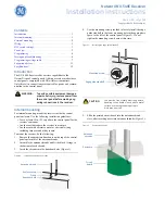
8. OPERATIONS AND SPECIFICATIONS
+
This Unit
Antenna jack
Rear output
Multi-CD player
(sold separately)
T
o
terminal always supplied with power
regardless of ignition switch position.
T
o
electric terminal controlled by ignition
switch (12 V DC) ON/OFF
.
Connecting cords with
RCA pin plugs
(sold separately)
Blue
Blue
T
o
system control terminal
of the power amp or Auto-
antenna relay control termi-
nal.
(Max. 300 mA 12 V DC)
Power amp
(sold separately)
Rear
Rear
≠
+
≠
Use this for connections
when you have the sepa-
rately available amplifier
.
T
o
vehicle (metal) body
.
+
Rear
Rear
≠
+
≠
+
+
Left speaker
Right speaker
Front
Front
≠
+
≠
Black (ground)
Red
Orange
Green
Green/black
Gray
Gray/black
Green/red
Black/green
Gray/red
Black/gray
With a 2 speaker system,
connect to the 2 speak-
ers in the front or the rear
.
+
Blue
Power amp
(sold separately)
Front
Front
≠
≠
See the section
“DFS Alarm Installation”
.
White
Brown
Rear output
Fuse
Front output
Fig. 26
Содержание KEH-P525
Страница 6: ...6 KEH P525 P5700 P5750 Fig 3 2 2 EXTERIOR ...
Страница 9: ...9 KEH P525 P5700 P5750 Fig 4 2 3 CASSETTE MECHANISM MODULE ...
Страница 11: ...11 KEH P525 P5700 P5750 ...
Страница 13: ...13 KEH P525 P5700 P5750 5 6 7 8 A B C D 5 6 7 8 A b A Fig 5 POWER AMP ...
Страница 14: ...14 KEH P525 P5700 P5750 A 1 2 3 4 B C D 1 2 3 4 A B A a A a A b ...
Страница 15: ...15 KEH P525 P5700 P5750 5 6 7 8 A B C D 5 6 7 8 C D E F Fig 6 A a A a A b C ...
Страница 16: ...16 KEH P525 P5700 P5750 A 1 2 3 4 B C D 1 2 3 4 POWER AMP A a A b A b ...
Страница 17: ...17 KEH P525 P5700 P5750 5 6 7 8 A B C D 5 6 7 8 Fig 7 A b A a A b ...
Страница 19: ...19 KEH P525 P5700 P5750 5 6 7 8 A B C D 5 6 7 8 B Fig 8 ...
Страница 20: ...20 KEH P525 P5700 P5750 A 1 2 3 4 B C D 1 2 3 4 3 3 CASSETTE MECHANISM MODULE A D D ...
Страница 21: ...21 KEH P525 P5700 P5750 5 6 7 8 A B C D 5 6 7 8 E F Fig 9 D E F ...
Страница 23: ...23 KEH P525 P5700 P5750 5 6 7 8 A B C D 5 6 7 8 B D CN251 CN901 SY Fig 10 SIDE A D B A ...
Страница 24: ...24 KEH P525 P5700 P5750 A 1 2 3 4 B C D 1 2 3 4 A A TUNER AMP UNIT ...
Страница 25: ...25 KEH P525 P5700 P5750 5 6 7 8 A B C D 5 6 7 8 Fig 11 A SIDE B ...
Страница 27: ...27 KEH P525 P5700 P5750 1 2 3 4 A B C D 1 2 3 4 Fig 13 C A CN601 SIDE B A CN601 C KEYBOARD UNIT ...
Страница 28: ...28 KEH P525 P5700 P5750 A 1 2 3 4 B C D 1 2 3 4 4 3 FM AM TUNER UNIT Fig 14 B B SIDE A FM AM TUNER UNIT A ...
Страница 29: ...29 KEH P525 P5700 P5750 1 2 3 4 A B C D 1 2 3 4 Fig 15 B B SIDE B FM AM TUNER UNIT ...
Страница 41: ...41 KEH P525 P5700 P5750 7 GENERAL INFORMATION 7 1 PARTS 7 1 1 IC TDA7384 TDA7386 PM2006A ...
Страница 45: ...45 KEH P525 P5700 P5750 7 1 2 DISPLAY CAW1477 Fig 22 COMMON SEGMENT ...
Страница 47: ...47 KEH P525 P5700 P5750 7 3 BLOCK DIAGRAM KEH P525 X1M UC Fig 25 D C B E A F ...
Страница 54: ......