Information on symptoms that do not constitute failure
SUPPLEMENT: On the video setting for HDMI
There are three types of HDMI output formats: color difference 4:4:4, color difference 4:2:2, and RGB4:4:4.
(The proportions, such as 4:4:4 and 4:2:2, represent those of the amount of data for video signal components. For example, as for color difference 4:4:4, the
proportion of the amount of data as for Y, Cb, and Cr is 4:4:4.)
It is required to make the settings of the PDP according to the settings of the output equipment. For usual operation, however, set them to AUTO. If the color is
inappropriate, make the settings manually.
In the HDMI system, video signals are coded at 24 bits per pixel and transmitted as a series of 24-bit pixels. In a case of color difference 4:4:4, Y, Cb, and Cr use
8 bits each. In a case of color difference 4:2:2, Y, Cb, and Cr use 12 bits each, but Cb and Cr are transmitted at a half sampling rate of Y. This unit is capable of
processing the upper 10 bits out of 12 bits of video data. Recent high-end DVD players, such as Pioneer DV-79AVi, are capable of outputting 10-bit color-
difference signals. In general, it is said that picture quality for color difference 4:2:2 format is assumed to be higher, because human eyes are more sensitive to
luminance than to colors. In the case of RGB4:4:4, R, G, and B use 8 bits each.
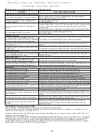
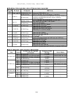
Symptom
Cause, item to check, information
HDMI: Symptoms concerning the input format and settings
The picture color for an INPUT 5 or 6 signal is not correct.
The color setting for INPUT 5 or 6 is not compatible with that of the output equipment.
Check whether the color setting is YPbPr or RGB.
The video signal to INPUT 5 or 6 is not displayed, and a
message is displayed.
A unsupported video signal is input.
Example: 1080p @ 60Hz
The audio signal input to the INPUT 5 or 6 pin jack is not
output.
The audio setting for INPUT 5 or 6 is "AUTO," and a video signal is not input. If the audio setting
is "AUTO," to output an analog audio signal, the DVI signal must be input via a DVI-HDMI
conversion cable.
When the DVI equipment is connected, the analog signals are selected with the setting "AUTO."
No sound of signals to INPUT 5 or 6 is output.
The setting on the side of the HDMI output equipment is wrong.
Example: Dolby Digital
MONITOR video output
The video output signal from the MONITOR connector is
deteriorated. Or when the video output signal from the MONITOR
connector is recorded, its playback picture is deteriorated.
The video signal output from the MONITOR connector is Macrovision protected.
The video signal is not output when the component signal is
input to INPUT 2, 3, or 4.
The video signal is not output from the MONITOR connector when the component signal is
selected.
The video signal is not output when the video signal is input
to INPUT 5 or 6.
The video signal is not output from the MONITOR connector when the HDMI signal is selected.
MONITOR audio output
The image displayed on the PDP is not synchronized with the
sound from the MONITOR audio output.
The audio signal from the MONITOR connector is synchronized with the video output signal from
the MONITOR connector.
DIGITAL audio output
Playback of the signal from the DIGITAL audio output
connector is possible, but recording is not possible.
The video signal output from the DIGITAL connector is copy-protected.
The video output signal from the DIGITAL connector is not
synchronized with that from the MONITOR video output.
The digital audio output signal from the DIGITAL connector is synchronized with the video signal
that is currently displayed, and not with the MONITOR video output.
Miscellaneous
The no-signal off function is not activated.
The no-signal off function is effective only while a video signal is being input.
The no-operation off function is not activated.
The no-operation off function is effective only while a video signal is being input.
Power management does not function.
Power management is effective only while a signal is being input from a PC.
The AUTO SETUP function is not activated.
The AUTO SETUP function is effective only while a signal is being input from a PC.
The G-Link system is not activated.
Wrong connection of the cable to the SR connector or PC audio connector is suspected.
Control via the SR connector is not possible.
A failure in the G-Link system or wrong connection of the cable to the PC audio connector is suspected.
The audio signal from the PC is not output.
A failure in the G-Link system or wrong connection of the cable to the SR connector is suspected.
The picture-quality setting (AV Selection) is not stored.
The picture-quality setting is stored for each input. As the setting is changed when another input
is selected, the user may have a false idea that the setting is not stored.
The picture size changes arbitrary.
The Auto Size setting is set to ON (default is OFF).
The display position of the screen slightly changes every time
the unit is turned on.
The orbiter function for minimizing the effects of phosphor burn is activated. As ON/OFF of this
function can only be changed on the Integrator menu, turning off of this function by a user is not
possible.
The video signal to the S video connector is not displayed.
Although S video input is selected on the menu, the cable is connected via a component video
input connector whose function type is the same as S video input.
The video signal to the composite video connector is not
displayed.
Although the composite video input is selected on the menu, the cable is connected via a
component video connector or S video connector whose function type is the same as the
composite video input.
96
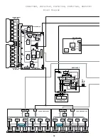
PDP4270HD, PDP4271HD, PDP5070HD, PDP5071HD, PRO507PU
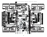
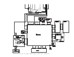
PDP6070HD, PDP6071HD, PRO607PU
Содержание Elite PRO-506PU
Страница 2: ......
Страница 8: ... 2 4 SI PG06003 A Warranty Claim Example 8 ...
Страница 14: ...14 Quick Reference G 3 to G 8 Power Down Shut Down Trap Switch Reset Service Remotes ...
Страница 23: ...23 Models PDP433PU PDP503PU Block Diagrams Shut Down Power Down Diagnosis ...
Страница 30: ...30 Models PDP433CMX PDP503CMX PDP4300 PRO800HD HDI PRO1000HD HDI ...
Страница 31: ...31 Block Diagrams Basic Service Factory Mode Shut Down Power Down Diagnosis ...
Страница 48: ...48 Models PDP434CMX PDP504CMX PDP505CMX PDP4304 PDP4314 PDP5004 PDP5014 PRO810HD PRO1010HD ...
Страница 49: ...49 Block Diagrams Operation LED Statuses Power Down Shut Down Diagnosis ...
Страница 59: ...59 Models PDP4350SX PDP5050SX Block Diagrams Operation LED Statuses Shut Down Power Down Diagnosis ...
Страница 72: ...72 Models PDP436PU PDP506PU PRO436PU PRO506PU ...
Страница 73: ...73 Block Diagrams Operation LED Statuses Shut Down Power Down Diagnosis System Reset ...
Страница 82: ...82 Models PDP4270HD PDP4271HD PDP5070HD PDP5071HD PDP6070HD PDP6071HD PRO507PU PRO607PU ...
Страница 83: ...83 Block Diagrams Quick Reference Power Down Shut Down Diagnosis System Reset Power Supply Jumper ...
Страница 87: ...87 Models PDP6070HD PDP6071HD PRO607PU Block Diagrams on the next two pages ...
Страница 99: ...99 Model PDP427CMX PDP507CMX PDP607CMX Block Diagrams Operation LED s Power Down Shut Down Diagnosis ...
Страница 120: ...120 Scan IC Troubleshooting Blue Glue Removal IC Removal ...
Страница 121: ......
Страница 142: ...142 ...


