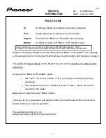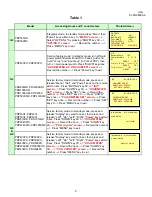
Trap Switch Reset Procedure
G-4, G-5, G-6, G-7
, G-8
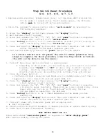
• Replace media receiver, plasma panel cover, or tape down HDCP trap switch.
If the model in question has the TV Guide option, the TV Guide
option
must
be turned off before proceeding.
• Using the customer’s remote control enter “
service mode
” by pressing the
following key sequence:
1. Press the
“display
” button then release the “
display
” button.
2. Wait between 3 and 7 seconds
3. Press and release the “
<
”, “
^
”, “
<
”, “
>
”, and “
power
” buttons in sequence.
• Panel will now turn on in “
service mode
”.
4. Press “
muting
” button 3, 4 or 5 times depending on model you are working on.
Until the display shows the “
initialize
” page.
5. Press and hold the “
display
” button until the error indicator (red LED) on
either the panel or the media receiver goes out.
6. Exit service mode by pressing the “
power
” button on the remote.
If a circuit failure will not permit the unit to remain powered-on long
enough to complete the above procedure, clear the Trap Switch as follows:
(You will not be able to see the menus.)
1. Turn off Main Power Switch on Panel or unplug panel.
•
Depending on which model you are working on, place switch on Digital
Assembly from "
Normal
" to "
Off
" or use a clip to short the high
voltage. Shorting connections located on upper right corner of
digital video board. (preventing high voltages from activating)
2. Place Main Power back on.
• Confirm both Media Receiver and Panel are in standby mode (unit that is
trapped will still have both red and green LEDs lit)
3. Press the “
display
” button then release the “
display
” button.
• Wait between 3 and 7 seconds
4. Press and release the “
<
”, “
^
”, “
<
”, “
>
”, and “
power
” buttons in sequence.
• Listen to panel carefully. There will be a very slight relay click.
Panel will now turn on in “service mode” with only the low
age supplies operating. (no picture)
volt
5. Press “
muting
” button 3, 4, or 5 times depending on the model you are
working on.
6. Press and hold the “
display
” button until the error indicator (red LED) on
either the panel or the media receiver goes out.
7. Turn soft power off, then main power off or unplug unit.
•
Wait 20 seconds
8. Return switch on Digital Assembly to Normal position or remove shorting clip.
9. Power back on and troubleshoot normally.
TRAP SWITCH RESET FOR G-3
Press and release “
menu,enter,power”
in sequence or “
enter,display,power”
Exit service mode by turning off power.
19
Содержание Elite PRO-506PU
Страница 2: ......
Страница 8: ... 2 4 SI PG06003 A Warranty Claim Example 8 ...
Страница 14: ...14 Quick Reference G 3 to G 8 Power Down Shut Down Trap Switch Reset Service Remotes ...
Страница 23: ...23 Models PDP433PU PDP503PU Block Diagrams Shut Down Power Down Diagnosis ...
Страница 30: ...30 Models PDP433CMX PDP503CMX PDP4300 PRO800HD HDI PRO1000HD HDI ...
Страница 31: ...31 Block Diagrams Basic Service Factory Mode Shut Down Power Down Diagnosis ...
Страница 48: ...48 Models PDP434CMX PDP504CMX PDP505CMX PDP4304 PDP4314 PDP5004 PDP5014 PRO810HD PRO1010HD ...
Страница 49: ...49 Block Diagrams Operation LED Statuses Power Down Shut Down Diagnosis ...
Страница 59: ...59 Models PDP4350SX PDP5050SX Block Diagrams Operation LED Statuses Shut Down Power Down Diagnosis ...
Страница 72: ...72 Models PDP436PU PDP506PU PRO436PU PRO506PU ...
Страница 73: ...73 Block Diagrams Operation LED Statuses Shut Down Power Down Diagnosis System Reset ...
Страница 82: ...82 Models PDP4270HD PDP4271HD PDP5070HD PDP5071HD PDP6070HD PDP6071HD PRO507PU PRO607PU ...
Страница 83: ...83 Block Diagrams Quick Reference Power Down Shut Down Diagnosis System Reset Power Supply Jumper ...
Страница 87: ...87 Models PDP6070HD PDP6071HD PRO607PU Block Diagrams on the next two pages ...
Страница 99: ...99 Model PDP427CMX PDP507CMX PDP607CMX Block Diagrams Operation LED s Power Down Shut Down Diagnosis ...
Страница 120: ...120 Scan IC Troubleshooting Blue Glue Removal IC Removal ...
Страница 121: ......
Страница 142: ...142 ...


