background image

25

AVX-505

-

Waveforms

1

Leading Waveform of T1 (Put probe near the T1)

AC 2V/div.     5µs/div.

2

U4-7

200mV/div.     2µs/div.

3

Q2-gate

1V/div.     2µs/div.

4

Q2-drain

5V/div.     2µs/div.

5

Q6-collector

20V/div.     5µs/div.

6

CP203

1V/div.     20µs/div.

7

CP204

1V/div.     5ms/div.

8

U501-17

1V/div.     50ns/div.

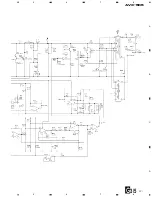
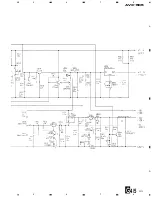
Note:The encircled numbers denote measuring pointes in the circuit diagram.

Содержание AVX-505

Страница 1: ...58 7 3 EXPLANATION 68 7 3 1 MECHANISM DESCRIPTIONS 68 7 3 2 BLOCK DIAGRAM 70 8 OPERATIONS AND SPECIFICATIONS 71 K FED APR 1998 Printed in Japan Precautions on Safety for Replacement of Backlight High voltage is generated in the inverter when the power is supplied to the system To avoid an electric shock reconfirm that the power switch is set to OFF before starting operation The fluorescent tube an...

Страница 2: ...oid the warranty If you are not qualified to perform the repair of this product properly and safely you should not risk trying to do so and refer the repair to a qualified service technician WARNING Lead in solder used in this product is listed by the California Health and Welfare agency as a known reproductive toxicant which may cause birth defects or other reproductive harm California Health and...

Страница 3: ...anual Model Part No Language AVX 505 UC CRD2679 English French 1 Cord Assy CDE5626 2 Cord Assy CDE5716 3 Accessory Assy CEA2467 4 Polyethylene Bag CEG1173 5 Polyethylene Bag CEG1116 6 Carton CHG3507 7 Contain Box CHL3507 8 Protector CHP2040 9 Protector CHP2041 10 Card ARY1048 11 Warranty Card Not used 12 Owner s Manual CRD2679 PACKING SECTION PARTS LIST Mark No Description Part No ...

Страница 4: ...465 4 Screw BMZ50P060FMC 5 Screw CBA 102 6 Screw CBA1002 7 Polyethylene Bag CEG 127 8 Screw CMZ50P060FMC 9 Nut NF50FMC 10 Polyethylene Bag CEG 158 11 Handle CNC5395 12 Strap CNF 111 13 Bush CNV1009 ACCESSORY ASSY PARTS LIST Mark No Description Part No 2 2 ACCESSORY ASSY ...

Страница 5: ...D 5 5 MONITOR 1 LCD 5 5 Monitor CWX2010 2 Rear Frame CZN3087 3 Screw PPZ20P040FMC 4 PCB Unit CZW3050 5 Sheet CZM3006 6 Side Frame CZN3008 7 Back Light Assy CZW3051 LCD 5 5 MONITOR PARTS LIST Mark No Description Part No ...

Страница 6: ...6 AVX 505 2 4 EXTERIOR 1 ...

Страница 7: ...Screw BPZ20P080FZK 23 Grille Assy CXB2377 24 LCD 5 5 Monitor CWX2010 25 Rail CNS4010 26 Rail CNS4011 27 Keyboard Unit CWM5896 28 Screw BPZ20P080FMC 29 Button CAC5180 30 Screw CBA1215 31 Spring CBH2099 32 Spring CBH2100 33 Spring CBH2107 34 Connector CKS2780 35 Holder CNC7643 36 Holder CNC7644 37 Holder CNC7645 38 Sheet CNM5032 39 PCB CNP5168 40 Arm CNV5311 41 Arm CNV5312 42 Arm CNV5313 43 Panel Un...

Страница 8: ...8 AVX 505 2 5 EXTERIOR 2 ...

Страница 9: ...Connector CN933 CKS3124 51 Connector CN934 CKS3124 52 Connector CN935 CKS3124 53 Connector CN937 CKS3125 54 Connector CN936 CKS3126 55 Bracket CNC6695 56 Insulator CNM5849 57 Cover CNC6506 58 Sheet CNM4892 59 Insulator CNM5001 60 Bracket Unit CXA8990 61 Gear Unit CXA8992 62 Bracket Unit CXA9007 63 Torque Limiter Assy CXA9624 64 Frame Unit CXA9627 65 Bracket Unit CXA9679 66 Case Unit CXB2591 67 Spa...

Страница 10: ...10 AVX 505 A 1 2 3 4 B C D 1 2 3 4 RESET A B A 3 SCHEMATIC DIAGRAM 3 1 MICRO COMPUTER UNIT Note When ordering service parts be sure to refer to EXPLODED VIEWS AND PARTS LIST or ELECTRICAL PARTS LIST ...

Страница 11: ...11 AVX 505 5 6 7 8 A B C D 5 6 7 8 A SPEAKER C AUDIO VISUAL MASTER UNIT ...

Страница 12: ...12 AVX 505 A 1 2 3 4 B C D 1 2 3 4 A 3 2 ENCODER UNIT C ...

Страница 13: ...13 AVX 505 5 6 7 8 A B C D 5 6 7 8 G E D F C C D E F ...

Страница 14: ...14 AVX 505 A 1 2 3 4 B C D 1 2 3 4 3 3 KEYBOARD UNIT B A B ...

Страница 15: ...15 AVX 505 ...

Страница 16: ...16 AVX 505 A 1 2 3 4 B C D 1 2 3 4 3 4 PCB UNIT LCD 5 5 MONITOR 1 5 G1 5 C CN939 ...

Страница 17: ...17 AVX 505 5 6 7 8 A B C D 5 6 7 8 G1 5 ...

Страница 18: ...18 AVX 505 A 1 2 3 4 B C D 1 2 3 4 2 5 G2 5 ...

Страница 19: ...19 AVX 505 5 6 7 8 A B C D 5 6 7 8 G2 5 ...

Страница 20: ...20 AVX 505 A 1 2 3 4 B C D 1 2 3 4 3 5 G3 5 ...

Страница 21: ...21 AVX 505 5 6 7 8 A B C D 5 6 7 8 G3 5 ...

Страница 22: ...22 AVX 505 A 1 2 3 4 B C D 1 2 3 4 4 5 G4 5 ...

Страница 23: ...23 AVX 505 5 6 7 8 A D 5 6 7 8 G4 5 ...

Страница 24: ...24 AVX 505 A 1 2 3 4 B C D 1 2 3 4 G5 5 5 5 ...

Страница 25: ...C 2V div 5µs div 2 U4 7 200mV div 2µs div 3 Q2 gate 1V div 2µs div 4 Q2 drain 5V div 2µs div 5 Q6 collector 20V div 5µs div 6 CP203 1V div 20µs div 7 CP204 1V div 5ms div 8 U501 17 1V div 50ns div Note The encircled numbers denote measuring pointes in the circuit diagram ...

Страница 26: ...26 AVX 505 9 VCK 1V div 20µs div 0 VSP1 1V div 5ms div VSP2 1V div 5ms div HCK 1V div 50ns div DLP 1V div 20µs div HSP1 1V div 20µs div HSP2 1V div 20µs div RSET 1V div 5ms div ...

Страница 27: ...7 AVX 505 COM 1V div 20µs div U901 10 2V div 2µs div Q902 collector 2V div 2µs div U901 7 1V div 2µs div Q905 drain 5V div 2µs div CN3 22 500mV div 20µs div TP302 2V div 20µs div TP202 500mV div 20µs div ...

Страница 28: ...28 AVX 505 fi U401 5 500mV div 20µs div fl CN1 14 200mV div 200µs div ...

Страница 29: ...29 AVX 505 ...

Страница 30: ...IAGRAMS 1 The parts mounted on this PCB include all necessary parts for several destination For further information for respective destinations be sure to check with the schematic diagram 2 Viewpoint of PCB diagrams Capacitor Connector P C Board Chip Part SIDE A SIDE B A A MICRO COMPUTER UNIT CN900 B ...

Страница 31: ...31 AVX 505 5 6 7 8 A B C D 5 6 7 8 RESET A SIDE A CN932 C SPEAKER CORD ASSY ...

Страница 32: ...32 AVX 505 A 1 2 3 4 B C D 1 2 3 4 A A MICRO COMPUTER UNIT ...

Страница 33: ...33 AVX 505 5 6 7 8 A B C D 5 6 7 8 A SIDE B ...

Страница 34: ...34 AVX 505 A 1 2 3 4 B C D 1 2 3 4 4 2 ENCODER UNIT C C ENCODER PCB C ENCODER PCB SIDE A SIDE B F VOLUME BRIGHT G ANGLE MOTOR G CN931 D POSITION MOTOR E CN1 ...

Страница 35: ...AVX 505 1 2 3 4 A B C D 1 2 3 4 LIFT SENSE ANGLE SENSE ANGLE 0 SIDE A SIDE B SIDE A SIDE B D ANGLE SENSE PCB D ANGLE SENSE PCB E LIFT SENSE PCB E LIFT SENSE PCB F ANGLE 0 PCB C CN937 C CN936 C CN935 D E F ...

Страница 36: ...36 AVX 505 A 1 2 3 4 B C D 1 2 3 4 4 3 KEYBOARD UNIT OPEN CLOSE B KEYBOARD UNIT B KEYBOARD UNIT B ...

Страница 37: ...37 AVX 505 5 6 7 8 A B C D 5 6 7 8 ANGLE DOWN ANGLE UP SIDE A SIDE B A CN100 B ...

Страница 38: ...38 AVX 505 A 1 2 3 4 B C D 1 2 3 4 4 4 PCB UNIT LCD 5 5 MONITOR G G PCB UNIT C CN939 ...

Страница 39: ...39 AVX 505 5 6 7 8 A B C D 5 6 7 8 G SIDE A ...

Страница 40: ...40 AVX 505 A 1 2 3 4 B C D 1 2 3 4 G PCB UNIT G ...

Страница 41: ...41 AVX 505 5 6 7 8 A B C D 5 6 7 8 G SIDE B ...

Страница 42: ...ransistor 2SA1832 D 1 Diode RD5R1UJ N2 D 2 Diode 1SS362 D 3 Diode 1SS362 D 4 Diode RD4R3UH D 5 Diode SB10 05PCP D 6 Diode RD5R1UJ N2 D 7 Diode 1SS362 D 8 Diode 1SS362 D 701 Diode RD4R7UJ N1 D 702 Diode RD4R7UJ N1 D 703 Diode RD4R7UJ N1 D 801 Diode RD4R3UH D 901 Diode RD5R1UJ N2 D 902 Diode 1SS362 D 903 Diode SB05 05CP D 904 Diode SB05 05CP D 905 Diode 1SS362 D 906 Diode SB05 05CP D 907 Diode SB05 ...

Страница 43: ...6S104J R 32 RMC1 16 512F CZC5111 R 33 RS1 16S562J R 34 NT732ATD10KΩJ CZC5098 R 35 RS1 16S104J R 36 RS1 16S104J R 38 RS1 16S104J R 39 RS1 16S103J R 40 RS1 16S105J R 41 RS1 10S471J R 42 RS1 16S2202F R 43 RS1 16S393J R 44 RS1 16S913J R 45 RS1 16S273J R 46 RS1 16S302J R 47 RS1 16S332J R 48 RS1 16S223J R 49 RS1 16S103J R 50 RS1 16S103J R 51 RS1 16S223J R 52 RS1 16S223J R 53 RS1 16S223J R 54 RS1 4S222J ...

Страница 44: ...6S0R0J R 540 RS1 16S0R0J R 541 RS1 16S0R0J R 545 RS1 16S0R0J R 548 RS1 16S0R0J R 549 RS1 16S0R0J R 550 RS1 16S0R0J R 551 RS1 16S101J R 557 RS1 16S0R0J R 558 RS1 16S750J R 559 RS1 16S750J R 560 RS1 16S750J R 561 RS1 16S750J R 562 RS1 16S750J R 563 RS1 16S750J R 564 RS1 16S750J R 565 RS1 16S750J R 566 RS1 16S750J R 567 RS1 16S750J R 568 RS1 16S750J R 569 RS1 16S750J R 570 RS1 16S750J R 571 RS1 16S75...

Страница 45: ...04Z25 C 22 CKSRYF104Z25 C 24 CKSRYB152K50 C 25 CX43Y5U106Z25B CZC5088 C 26 CCSRCH102J50 C 27 CKSQYB332K50 C 28 CX43Y5U106Z25B CZC5088 C 29 CX43Y5U106Z25B CZC5088 C 30 CKSRYF104Z25 C 31 CM32Y5V105Z50A CZC5086 C 32 CKSRYB562K50 C 101 SVHD21A336M CZC5091 C 102 CKSRYF104Z25 C 103 CCSRCH470J50 C 104 CCSRCH680J50 C 105 CKSRYF104Z25 C 106 CKSRYF104Z25 C 107 CKSRYF104Z25 C 108 CKSRYF104Z25 C 110 CM32Y5V10...

Страница 46: ...umber CWM5895 Unit Name Micro Computer Unit MISCELLANEOUS IC 300 IC PD4703C IC 301 IC NJM4558M IC 302 IC S 80734ANDYI IC 400 IC NJM7809FA IC 401 IC M54649L Q 101 Transistor 2SC2412K Q 102 Transistor 2SC2412K Q 200 Transistor 2SA1162 Q 201 Transistor 2SC2412K Q 202 Transistor DTA124EK Q 203 Transistor 2SC2412K Q 204 Transistor 2SC2412K Q 205 Transistor 2SD1664 Q 206 Transistor 2SA1797 Q 207 Transis...

Страница 47: ...S1 10S563J R 330 RS1 10S824J R 331 RS1 10S222J R 332 RS1 10S224J R 333 RS1 10S224J R 334 RS1 10S473J R 335 RS1 10S223J R 336 RS1 4S681J R 341 RS1 10S103J R 342 RS1 10S103J R 343 RS1 10S103J R 400 RS1 10S103J R 401 RS1 4S102J R 402 RS1 10S471J R 405 RA3C102J R 406 RS1 4S102J R 500 RS1 10S103J R 501 RS1 10S103J R 502 RS1 10S223J R 503 RS1 10S473J R 504 RS1 10S472J R 508 RS1 10S103J R 509 RS1 10S473J...

Страница 48: ...10S473J R 940 RS1 10S224J R 942 RS1 10S473J R 943 RS1 10S473J R 944 RS1 4S331J R 950 RS1 10S0R0J R 952 RS1 10S133J R 953 RS1 10S103J R 954 RS1 10S472J R 955 RS1 10S133J R 956 RS1 10S102J R 957 RS1 10S622J R 958 RS1 10S622J R 959 RS1 10S224J R 960 RS1 10S224J R 961 RS1 10S223J R 962 RS1 10S223J CAPACITORS C 933 1000µF 10V CCH1184 C 938 CSZST220M16 C 939 CSZSC100M16 C 940 CKSQYB102K50 C 941 CKSQYB10...

Страница 49: ...TP305 waveform b 9 0 0 1 V VR302 2 TP304 voltage Should be within the range of 2 5 0 5 V and generate the greatest difference between voltages of tone 0 and 1 of output waveforms of TP302 VR301 3 TP702 waveform a b voltage 3 1 0 05 V VR304 b c voltage 0 0 05 V VR307 4 TP701 waveform a b voltage 3 1 0 05 V VR305 b c voltage 0 0 05 V VR308 5 TP703 waveform a b voltage 3 1 0 05 V VR306 b c voltage 0 ...

Страница 50: ...ontrol output 49 MTRSEL O C Motor position control output 50 IOPULS I Monitor position sense control input 51 deg sw I 0 degree switch input 52 liftsw I Lift switch input 53 DEGPULS I Monitor degree sense input 54 vinmcc I Not used 55 PBSENS I Not used 56 TX O C Not used 57 RX I Not used 58 ad SOC I Not used 59 ilmin I Illumination power sense input 60 reset I Reset input 61 NC Not used 62 bsens I...

Страница 51: ...A to remove the Panel 2 Remove the four screws B 3 Upright the tabs in two places indicated with arrows 4 Lift the Micro Computer Unit to remove the conn ector Remove the Micro Computer Unit Micro Computer Unit A A A B B B B C D C Cover Chassis Assy Monitor Panel Unit PCB Connector E F E F Rail F F F E E F LCD Assy Removing the LCD Assy 1 Remove the two connectors 2 Remove the four screws E Remove...

Страница 52: ...ve the Guide 2 Remove the Gear Unit Removing the Lift Sense PCB 1 Remove the connector 2 Remove screw M to remove the Lift Sense PCB Removing the Angle Sense PCB 1 Remove the connector 2 Remove screw N to remove the Angle Sense PCB Removing the Encoder PCB 1 Upright the tabs in two places indicated with arrows 2 Remove screw O to remove the Encoder PCB Shaft G H Spring Case Unit Angle Motor K K J ...

Страница 53: ... incorrect operation of the Monitor Precautions on assembly of the Drive Mecha nism Unit 1 Insert the Drive Mechanism Unit into the Rail Units L and R Pushing the Drive Mechanism Unit toward the left facilitates insertion 2 Push the Drive Mechanism Unit with applying the same force to the right and left 3 Check the mark on the Chassis Assy to confirm that the Drive Mechanism Unit is inserted corre...

Страница 54: ...026xxx For quality control of the LCD 5 5 Monitor write down Substrate Unit Adjust flicker in advance Backlight Assy Replacement should be made according to page 57 Side frame Same as above Precautions after replacement of parts of the LCD 5 5 Monitor Product name Lot No Panel No Rear frame ...

Страница 55: ... hole precision screwdriver etc 2 Do NOT damage the electrical parts on the PCB Unit 5 Remove the flexible PCB shown as b and the connector shown as c in Fig 6 Note Do NOT damage the flexible PCB 6 Remove the PCB Unit Note Do NOT damage the electrical parts on the PCB Unit 7 Remove the protection sheet Note Do NOT damage the protection sheet 8 Lightly insert a flat tip screwdriver into the gaps th...

Страница 56: ...Notes 1 Use a screwdriver matching the screw hole precision screwdriver etc 2 Do NOT damage the electrical parts on the PCB Unit 18 Insert the holes into the gaps three places indicated as a in Fig 5 to install the rear frame Note Do NOT deform the rear frame 4 Disposal of the Backlight Assy The Backlight Assy uses a cold cathode tube Follow the local regulations when disposing the Backlight Assy ...

Страница 57: ...ct The cables of the flexible PCB and backlight may be broken Take adequate care when handling the product The cold cathode tube of the Backlight Assy is made of glass Applying shock or abnormal stress may damage the tube Take adequate care when handling the Backlight Assy When removing the Backlight Assy Remove insert the Backlight Assy straight so that no excessive stress is applied to the assem...

Страница 58: ...ower and correct Correct the dimmer voltage Replace F1 Replace back light NO NO NO YES YES YES NO Abnormal YES Normal Put probe of oscilloscope near the yellow tape of T1 High voltage Is CN4 completely inserted A1 Insert CN4 completely NO NO YES YES Be careful for high voltage Be sure to turn the power OFF then check Check the waveform waveform 1 7 2 2 TROUBLESHOOTING FOR LCD 5 5 MONITOR ...

Страница 59: ...k the voltage of Q11 collector Is the voltage 0 5 V or lower Check the waveform of U4 7 Check the waveform of Q2 gate Check the waveform of Q2 drain Replace Q8 Q9 and Q10 Replace U4 then readjust 1 1 Check the waveform waveform 2 Replace Q2 Check the waveform waveform 3 Check the waveform waveform 4 A1 NO NO NO NO NO YES YES YES YES YES To the next page ...

Страница 60: ...ower Check the voltage of TP7 Is the voltage 8 1 0 V Check the waveform of Q6 collector From the previous page Replace U3 Replace U2 Replace Q6 and Q7 Malfunction cannot be identified Return to the manufacturer NO NO NO YES YES YES Check the waveform waveform 5 ...

Страница 61: ... the voltage of TP103 Is the voltage 5 0 5 V Check the voltage of TP104 Is the voltage 12 5 1 0 V Display shows white screen when the power is turned ON Check the system power and correct Connect CN1 and CN3 correctly Replace F901 Replace U903 To the next page B1 NO NO NO NO NO YES YES YES YES Check the voltage of TP105 Is the voltage 18 1 0 V B2 NO YES YES ...

Страница 62: ...m of U501 17 Check the waveform of CN3 From the previous page Replace U201 Replace U601 Replace U501 The panel is defective Return to the manufacturer NO NO NO YES YES YES Check the waveform waveform 9 Check the waveforms waveforms 6 and 7 Check the waveform waveform 8 ...

Страница 63: ...ified Return to the manufacturer NO NO NO YES YES YES Check the waveform waveform Check the waveform waveform Check the voltage of Q904 collector Is the voltage 9 5 1 5 V Check the waveform of U901 7 Check the waveform of Q905 drain B2 Replace Q904 Replace U901 then readjust 2 12 Replace U902 and Q905 Malfunction cannot be identified Return to the manufacturer NO NO NO YES YES YES Check the wavefo...

Страница 64: ...ge 8 1 0 V Contrast has deteriorated NO Abnormal YES Normal NO Abnormal YES Normal Replace Q908 and Q910 then readjust 2 4 Replace Q906 and Q907 then readjust 2 3 The panel is defective Return to the manufacturer A line or block is missing The panel is defective Return to the manufacturer NO NO YES YES ...

Страница 65: ...ot be identified Return to the manufacturer Replace Q705 and Q709 Replace U301 then readjust 3 1 to 8 and 4 Replace U401 Check the waveform waveform fi Check the waveform waveform fl Check the waveform waveform Check the waveform waveform Check the waveform waveform Replace Q405 No signal sent from the system Check the waveform of TP302 YES YES YES YES YES NO NO NO NO NO ...

Страница 66: ...t be identified Return to the manufacturer Replace Q704 and Q708 Replace U301 then readjust 3 1 to 8 and 4 Replace U401 Check the waveform waveform fi Check the waveform waveform fl Check the waveform waveform Check the waveform waveform Check the waveform waveform Replace Q404 No signal sent from the system Check the waveform of TP301 YES YES YES YES YES NO NO NO NO NO ...

Страница 67: ...ot be identified Return to the manufacturer Replace Q706 and Q710 Replace U301 then readjust 3 1 to8 and 4 Replace U402 Check the waveform waveform fi Check the waveform waveform fl Check the waveform waveform Check the waveform waveform Check the waveform waveform Replace Q406 No signal sent from the system Check the waveform of TP303 YES YES YES YES YES NO NO NO NO NO ...

Страница 68: ...igh speed when the Position Sensing switch Lift switch in the forward backward direction is set to OFF 3 The system stops the angle motor after the angle encoder pulses are output for 12 waves Brake mode If the previous angle is saved in the memory the system moves the angle motor to that angle 4 The system operates the position motor at low speed approximately 1 second after the monitor is positi...

Страница 69: ...he position motor to the utmost end at slow speed The system moves the angle motor for 1 wave of angle pulse in Slow mode 1 second after forward backward pulses cease to be output Then the system enters Brake mode 2 After approximately 3 seconds the system moves the position motor at slow speed and stops the motor when forward backward pulse is not output Brake mode The system operates in the same...

Страница 70: ...70 AVX 505 7 3 2 BLOCK DIAGRAM ...

Страница 71: ... Brightness control Volume control Signal receptor OPEN CLOSE button ANGLE button DETACH button Monitor Fuse resistor Fuse holder Fuse resistor Orange To terminal always supplied with power regardless of ignition switch position Red To electric terminal controlled by ignition switch 12 V DC ON OFF Black ground To vehicle metal body Yellow To lighting switch terminal This Product AUDIO VISUAL MASTE...

Страница 72: ...0 H 165 D mm 7 W 2 H 6 1 2 D in nose 170 W 47 4 H 25 1 D mm 6 3 4 W 1 7 8 H 1 D in max salient dimension 163 1 mm 6 3 8 in monitor 156 W 124 6 H 23 5 D mm 6 1 8 W 4 7 8 H 7 8 D in Weight 1 6 kg 3 5 lbs Monitor Screen size 5 5 in dia effective display area 83 5 111 36 mm Pixels 224 640 Type TFT active matrix transmissive type Operation temperature range 10 50 C Storage temperature range 20 80 C Ang...

Отзывы: