AVH-P3100DVD/XN/UC
101
5
6
7
8
5
6
7
8
C
D
F
A
B
E
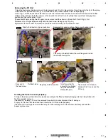
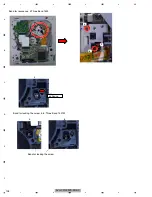
Fig. 2a
Permanently hooked position Temporary hooked position
Fig. 2b
A
Slide to the direction of inner periphery
Fig. 1
Fig. 3
B
Fig.4
Regularly installed position
Install avoiding the
area with blue broken
line (the connected
metal plate part)
The spring is installed under the resin flange and inside
the bended metal plate.
Outside holder
Back end of
the feed screw
Removing the PU Unit
1.Hook the feed screw biasing spring on the temporary hook (Fig. 2b). Be careful not to get injured by the tip of the spring.
2.Hold the PU at the location A in Fig. 1 and slide and scoot it to the direction of the inner periphery.
3.As in Fig. 3, shift the back end of the feed screw to the side and then to above and remove it from the outside holder.
4.Remove the tucking joint for the chassis at the location B and the PU unit by lifting them up without changing their
position and then remove the PU unit.
(Precaution) When installing the PU again, make sure to tuck the chassis in B and the PU unit (Fig. 4) first.
Moreover, do not forget to permanently hook the feed screw biasing spring (Fig. 2a).
Adjustments to the PU after its installation should be made according to the service manual.
Sending the PU to the outer periphery
1.Bring to the clamp state with no disc loaded according to the “Mecha Module_Bringing into the Clamp State with
No Disc Loaded” manual.
(Precaution) The relay FFC must be removed for certainty in order to prevent the IC damage.
2.Apply 1.5V to the CRG motor and then transfer the PU to the outer periphery.
(Precaution) Do not forget to reinstall the relay FFC after sending the PU to the outer periphery and take the
necessary measures.
[Installation NG]
The chassis is not tucked
between the PU case and the
PU rack.
Содержание AVH-P3150DVD
Страница 29: ...AVH P3100DVD XN UC 29 5 6 7 8 5 6 7 8 C D F A B E ...
Страница 56: ...AVH P3100DVD XN UC 56 1 2 3 4 1 2 3 4 C D F A B E Side A COMPOSITE GNDV Fig 11 3 VIDEO signal check point ...
Страница 59: ...AVH P3100DVD XN UC 59 5 6 7 8 5 6 7 8 C D F A B E Side A DGND1 IC1501 50pin Fig 13 3 48 MHz check point ...
Страница 61: ...AVH P3100DVD XN UC 61 5 6 7 8 5 6 7 8 C D F A B E Side A SCLOCK SDATA D CP_ RESET D DGND2 ...
Страница 67: ...AVH P3100DVD XN UC 67 5 6 7 8 5 6 7 8 C D F A B E ...
Страница 114: ...AVH P3100DVD XN UC 114 1 2 3 4 1 2 3 4 C D F A B E 9 1 PACKING ...
Страница 116: ...AVH P3100DVD XN UC 116 1 2 3 4 1 2 3 4 C D F A B E 9 2 EXTERIOR 1 A A A B ...
Страница 118: ...AVH P3100DVD XN UC 118 1 2 3 4 1 2 3 4 C D F A B E 9 3 EXTERIOR 2 A A E F 2 1 ...
Страница 122: ...AVH P3100DVD XN UC 122 1 2 3 4 1 2 3 4 C D F A B E A GEM1045 B GEM1038 C GEM1024 A C C A A C C C C C A A ...
Страница 123: ...AVH P3100DVD XN UC 123 5 6 7 8 5 6 7 8 C D F A B E ...
Страница 127: ...AVH P3100DVD XN UC 127 5 6 7 8 5 6 7 8 C D F A B E ...
Страница 145: ...AVH P3100DVD XN UC 145 5 6 7 8 5 6 7 8 C D F A B E ...


