PNOZ s11
Operating Manual PNOZ s11
21693-EN-11
| 10
Wiring
Please note:
}
" must be followed.
}
Outputs 13-14, 23-24, 33-34, 43-44, 63-64, 73-74, 83-84, 93-94 are safety contacts; out-
put 51-52 is an auxiliary contact (e.g. for display).
}
Auxiliary contact 51-52 should
not
be used for safety circuits!
}
To prevent contact welding, a fuse should be connected before the output contacts (see
}
Calculation of the max. cable length l
max
in the input circuit:
R
lmax
R
l
/ km
I
max
=
R
lmax
= max. overall cable resistance (see
)
R
l
/ km = cable resistance/km
}
Use copper wiring with a temperature stability of 75 °C.
}
To prevent EMC interferences (particularly common-mode interferences) the measures
described in EN 60204-1 must be executed. This includes the separate routing of cables
of the control circuits (input, start and feedback loop) from other cables for energy trans-
mission or the shielding of cables, for example.
}
Adequate protection must be provided on all output contacts with capacitive and inductive
loads.
}
The power supply must comply with the regulations for extra low voltages with protective
electrical separation (SELV, PELV) in accordance with VDE 0100, Part 410.
Preparing for operation
Supply voltage
AC
DC
A1
A2
24 V DC
0 V
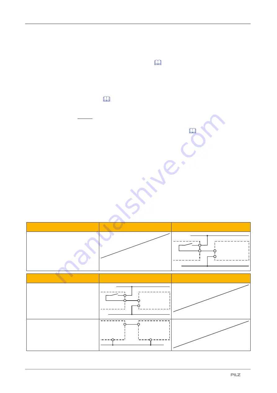
PNOZsigma
expansion
module
Input circuit
Single-channel
Dual-channel
Base unit:
Safety relay PNOZ X
A1
A2
24 V DC
0 V
PNOZsigma
expansion
module
Base unit:
Safety relay PNOZelog
Driven via semiconductor outputs
(24 VDC)
A1
A2
0 V
O1
L-
PNOZsigma
expansion
module


