background image

PNOZ 15

Operating Manual PNOZ 15
18492-EN-04

19

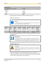
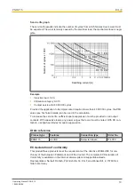
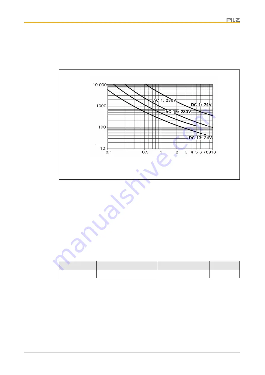
Service life graph

The service life graphs indicate the number of cycles from which failures due to wear must
be expected. The wear is mainly caused by the electrical load; the mechanical load is negli-
gible.

Number of cycles x 1000

Switching current (A)

Example

}

Inductive load: 0.2 A

}

Utilisation category: AC15

}

Contact service life: 4 000 000 cycles

Provided the application to be implemented requires fewer than 4 000 000 cycles, the PFH
value (see Technical details) can be used in the calculation.
To increase the service life, sufficient spark suppression must be provided on all output
contacts. With capacitive loads, any power surges that occur must be noted. With DC con-
tactors, use flywheel diodes for spark suppression.

Order reference

Product type

Features

Connection type

Order No.

PNOZ 15

24 VDC

Screw terminals

774 050

EC declaration of conformity

This product/these products meet the requirements of the directive 2006/42/EC for ma-
chinery of the European Parliament and of the Council. The complete EC Declaration of
Conformity is available on the Internet at www.pilz.com/support/downloads.
Representative: Norbert Fröhlich, Pilz GmbH & Co. KG, Felix-Wankel-Str. 2, 73760 Ost-
fildern, Germany

Содержание PNOZ 15

Страница 1: ...PNOZ 15 Operating Manual 18492 EN 04 Safety relays...

Страница 2: ...nta tion will be gratefully received Source code from third party manufacturers or open source software has been used for some components The relevant licence information is available on the Internet...

Страница 3: ...liability 6 Disposal 6 For your safety 6 Unit features 7 Safety features 7 Block diagram terminal configuration 7 Function Description 8 Operating modes 8 Timing diagram 9 Installation 9 Wiring 10 Pr...

Страница 4: ...y important is identified as follows DANGER This warning must be heeded It warns of a hazardous situation that poses an immediate threat of serious injury and death and indicates preventive measures t...

Страница 5: ...nt electrical installation The product is designed for use in an industrial environment The product may cause interference if installed in other environments If installed in other environments measure...

Страница 6: ...e generic and specialist standards applicable to the spe cific application Warranty and liability All claims to warranty and liability will be rendered invalid if The product was used contrary to the...

Страница 7: ...fety relay meets the following safety requirements The circuit is redundant with built in self monitoring The safety function remains effective in the case of a component failure The correct opening a...

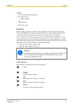
Страница 8: ...nternal fuse thermal circuit breaker has not blown If there is a fault on the safety relay a high signal is present at Y35 the FAULT LED lights Once the cause of the fault has been removed the fuse mu...

Страница 9: ...normally open Out semi FAULT Semiconductor output fault 1 Automatic start 2 Manual start a Input circuit closes before start circuit b Start circuit closes before input circuit t1 Switch on delay t2...

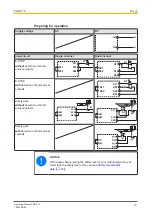
Страница 10: ...s with capacitive and in ductive loads The power supply must comply with the regulations for extra low voltages with protect ive electrical separation SELV PELV in accordance with VDE 0100 Part 410 En...

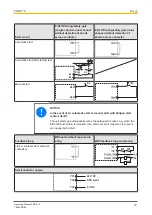
Страница 11: ...S12 S1 S11 S12 S52 S22 S21 E STOP with detection of shorts across contacts S1 S22 S21 S12 S11 S52 S11 Safety gate without detection of shorts across contacts S1 S22 S21 S11 S52 S12 S1 S2 S22 S21 S11...

Страница 12: ...t up test S2 S1 S33 S34 Manual start S33 S34 S3 NOTICE In the event of an automatic start or manual start with bridged start contact fault The unit starts up automatically when the safeguard is reset...

Страница 13: ...t the safety contacts on the relay outputs open correctly Open the safety contacts switch off output and start the device again so that the internal diagnostics can check that the safety contacts open...

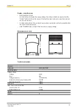
Страница 14: ...ons If the contacts have welded reactivation will not be possible after the input circuit has opened LED POWER does not light Short circuit or no supply voltage Dimensions in mm 121 4 76 75 2 95 87 3...

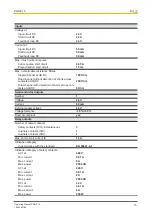
Страница 15: ...nnel with detection of shorts across con tacts at UB DC 5 Ohm Semiconductor outputs Number 1 Voltage 24 V Current 50 mA External supply voltage 24 V Voltage tolerance 30 30 Short circuit proof yes Rel...

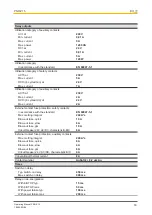
Страница 16: ...ent 2 A External contact fuse protection safety contacts In accordance with the standard EN 60947 5 1 Max melting integral 240 A s Blow out fuse quick 10 A Blow out fuse slow 6 A Blow out fuse gG 10 A...

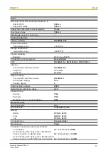
Страница 17: ...Frequency 10 55 Hz Amplitude 0 35 mm Airgap creepage In accordance with the standard EN 60947 1 Overvoltage category III II Pollution degree 2 Rated insulation voltage 400 V Rated impulse withstand vo...

Страница 18: ...function must be considered when calculating the safety characteristic data INFORMATION A safety function s SIL PL values are not identical to the SIL PL values of the units that are used and may be d...

Страница 19: ...sed in the calculation To increase the service life sufficient spark suppression must be provided on all output contacts With capacitive loads any power surges that occur must be noted With DC con tac...

Страница 20: ...fetyNET p THE SPIRIT OF SAFETY are registered and protected trademarks of Pilz GmbH Co KG in some countries We would point out that product features may vary from the details stated in this document d...

Отзывы: