background image

Preface

This document is the original document.
All rights to this documentation are reserved by Pilz GmbH & Co. KG. Copies may be made
for the user's internal purposes. Suggestions and comments for improving this documenta-
tion will be gratefully received.
Source code from third-party manufacturers or open source software has been used for
some components. The relevant licence information is available on the Internet on the Pilz
homepage.
Pilz®, PIT®, PMI®, PNOZ®, Primo®, PSEN®, PSS®, PVIS®, SafetyBUS p®,
SafetyEYE®, SafetyNET p®, the spirit of safety® are registered and protected trademarks
of Pilz GmbH & Co. KG in some countries.

 SD means Secure Digital

Содержание PMCprimo MC

Страница 1: ...PMCprimo MC Operating Manual 1003813 EN 03 Control systems...

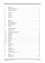
Страница 2: ...nta tion will be gratefully received Source code from third party manufacturers or open source software has been used for some components The relevant licence information is available on the Internet...

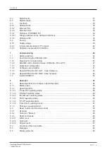
Страница 3: ...s 13 4 Function description 14 4 1 Device properties 14 4 1 1 Controller 14 4 1 1 1 Networking with servo amplifier 15 4 1 2 Connecting the supply voltage 17 4 1 3 Digital inputs 18 4 1 4 Digital outp...

Страница 4: ...basic configuration 50 7 2 4 Configure servo amplifier 51 7 2 5 Operate PMCprimo MC HW1 Show Hardware 52 7 2 6 Operate PMCprimo MC HW2 Show hardware 54 7 3 Install CODESYS 54 8 Operation 55 8 1 Operat...

Страница 5: ...Contents Operating Manual PMCprimo MC 1003813 EN 03 5 9 Technical details 65 10 Order reference 69 10 1 Product 69 10 2 Accessories 69...

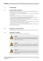
Страница 6: ...r motion control devices e g CODESYS PASmotion can be found on the Internet at www pilz com You will need to be conversant with the information in these documents in order to fully un derstand this op...

Страница 7: ...n in which the product or devices could be dam aged and also provides information on preventive measures that can be taken It also highlights areas within the text that are of particular import ance I...

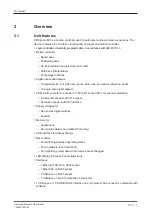
Страница 8: ...puts 16 single pole digital outputs 2 3 Mini I O sockets for encoder or 1 Mini I O socket X41 for encoder emulation Incremental encoder with TTL signal Absolute encoder with SSI interface Supply volta...

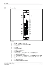
Страница 9: ...tton and LEDs to display operating states 3 X46 USB interface 4 X45 unused 5 X44 EtherCAT interface 6 X43 Ethernet TCP IP interface 7 X42 CANopen interfaces 8 X41 Connection for encoder 1 or in emulat...

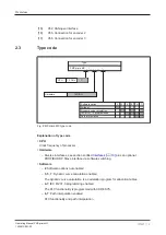
Страница 10: ...ig PMCprimo MC type code Explanation of type code CPU Clock frequency of processor Hardware Diverse interfaces see section entitled Interfaces 19 plus an optional PROFIBUS DP Slave interface via softw...

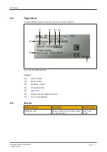
Страница 11: ...controller 1 2 3 4 5 6 7 Fig Type label PMCprimo MC Legend 1 Order number 2 Serial number 3 Hardware version 4 Firmware version 5 Type code 6 Supply voltage voltage tolerance 7 Year of manufacture 2 5...

Страница 12: ...res should be taken to comply with the applicable standards and directives for the respective installation site with regard to in terference 3 2 Safety regulations 3 2 1 Use of qualified personnel The...

Страница 13: ...When decommissioning please comply with local regulations regarding the disposal of electronic devices e g Electrical and Electronic Equipment Act 3 3 Standards To use the device correctly you will n...

Страница 14: ...PLC functionality The motion controller has 16 digital inputs and 16 single pole digital outputs The inputs and outputs are read cyclically The cycle time is 1ms It can also access inputs and out put...

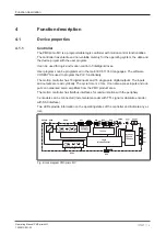
Страница 15: ...tocol CANopen Via the interface X52 9 pin D Sub To create a connection a fieldbus distributor PMCprotego D CAN Adapter 2 is required with the servo amplifier PMCprotego D X40a X50a b PMCprotego D CAN...

Страница 16: ...Motion controller with servo amplifier networking via CANopen Networking of PMCprimo MC 1 with the servo amplifier PMCprotego D 3 Via the communication protocol EtherCAT Via the interface X44 RJ45 The...

Страница 17: ...a Pin 3 and X50b Pin 3 0 V X50a Pin 2 and X50b Pin 2 X50a Pin 4 and X50b Pin 4 X46 USB SNet CAN1 X45 Out X43 In X44 SNet RESET ETH FUNC X41 ENC1 STAT CAN2 X56 ENC2 X55 ENC3 X52 CAN3 X51 CAN4 X50c X50b...

Страница 18: ...coder when the encoder input is used in emulation mode as an output Further information on the emulation mode is available at Encoder emulation 23 4 1 3 Digital inputs The device has 16 digital inputs...

Страница 19: ...e on RJ45 sockets on the front of the device or 9 pin D Sub connections The interfaces are suitable for the following applications CANopen Real time capable networking between CAN devices and the moti...

Страница 20: ...by the motion controller are ready for operation immediately after the initial network run up No complex configuration of the CAN devices is required The overall line length and the length of the stu...

Страница 21: ...l Address space of bus variables B1 to Bx108 can be set using the CD command Data width 16 Bit including sign Value range 32768 to 32767 Hex 0x0000 bis 0x7FFF INFORMATION The GSD file is available on...

Страница 22: ...nces can be detected and localised with EtherCAT even if the interference does not influence the functionality of the machine 4 1 5 6 USB INFORMATION Use a USB stick with FAT32 formatting The USB inte...

Страница 23: ...coder emulation Prerequisite Motion Controller from Firmware version 0305 see Type label 11 To interconnect motion controllers and to be able to synchronise the position the encoder input X41 can be u...

Страница 24: ...s 4 1 8 Reset button The RESET button is mounted in a recess on the front of the unit It can only be accessed using an appropriate tool e g a pin The following actions can be triggered by pressing the...

Страница 25: ...of the motion controller Oscilloscope function PScope is a PC based oscilloscope with up to 4 channels It can be used to record and visualise signals from controllers and servo amplifiers Elliptical c...

Страница 26: ...ICE Damage due to electrostatic discharge Electrostatic discharge can damage components Ensure against discharge before touching the product e g by touching an earthed conductive sur face or by wearin...

Страница 27: ...ool Hexagonal wrench 4 mm Follow the instructions below Drill M5 holes in the control cabinet s mounting plate as shown in the illustrations Attach the device to the control cabinet s mounting plate w...

Страница 28: ...nto the servo amplifier INFORMATION Pin assignment wiring and assembly are described in the operating manual for the fieldbus junction box To install the fieldbus junction box follow the instructions...

Страница 29: ...from the output to the load and a supply line it will no longer be possible to switch off the load Possible remedy Use separate multicore cable for supply voltages Use appropriate wiring to exclude sh...

Страница 30: ...isolating trans former If the link is removed earth fault monitoring must be used in accordance with EN 60204 VDE 0113 Connector X50a X50b Pin Designation Description X50a X50b 1 24 V Supply voltage 2...

Страница 31: ...ital fast input 3 4 I1 4 Digital fast input 4 9 I1 5 Digital fast input 5 10 I1 6 Digital fast input 6 11 I1 7 Digital input 7 12 I1 8 Digital input 8 X40a 3 0 V Reference earth for digital inputs Inp...

Страница 32: ...ital input 3 4 I2 4 Digital input 4 9 I2 5 Digital input 5 10 I2 6 Digital input 6 11 I2 7 Digital input 7 12 I2 8 Digital input 8 X50b 3 0 V Reference earth for digital inputs X50a 3 0 V Reference ea...

Страница 33: ...2 Digital output 2 7 O1 3 Digital output 3 8 O1 4 Digital output 4 13 O1 5 Digital output 5 14 O1 6 Digital output 6 15 O1 7 Digital output 7 16 O1 8 Digital output 8 X40a 1 24 V Supply voltage for di...

Страница 34: ...igital output 4 13 O2 5 Digital output 5 14 O2 6 Digital output 6 15 O2 7 Digital output 7 16 O2 8 Digital output 8 X50a X50b 1 24 V Supply voltage for digital outputs 3 0 V supply Reference earth for...

Страница 35: ...gh signal 5 CAN2_L CAN2 low signal 6 GND Ground 7 CAN_H CAN1 high signal 8 CAN_L CAN1 low signal n c not connected Device type 2 CANopen interfaces Connection via fieldbus junction box on the servo am...

Страница 36: ...ht design with axial cable routing as the PROFIBUS connector CANopen connector The PROFIBUS DP and CANopen interface are on the same socket The PROFIBUS DP and CANopen interface use the same operating...

Страница 37: ...cture The overall line length and the length of the stub lines depend on the transmission rate and on the cable properties cable resistance and cable capacitance The signal lines must be terminated wi...

Страница 38: ...of the terminating resistor RT with different cable lengths In each specific case details of the characteristic imped ance can be found in the cable specification Bus length l m Terminating resistor R...

Страница 39: ...used in emulation mode as an output See information on encoder emulation 23 Connector X40a Pin Designation Description X40a 2 Encoder Supply Supply voltage for ex ternal encoder 4 0 V Encoder Supply...

Страница 40: ...earth fault monitoring must be used in accordance with EN 60204 VDE 0113 6 6 2 Incremental encoder with TTL signal If the cable length is 50 m please speak to our Customer Support Mini I O socket X41...

Страница 41: ...3 EN 03 41 Input circuit Incremental encoder 5 6 X40a 2 4 Shield Encoder supply Twisted pair shielded Shield connection in the housing 5 6 X50b 2 4 Shield X50a 2 4 X55 X56 Encoder supply Twisted pair...

Страница 42: ...O socket X41 X55 X56 Pin Designation Description 8 6 4 2 7 5 3 1 1 V Supply voltage 2 0 V Supply voltage 0 V 3 n c 4 CLOCK Pulse signal 5 CLOCK Pulse signal inverted 6 n c 7 DATA Data 8 DATA Data inv...

Страница 43: ...iring Operating Manual PMCprimo MC 1003813 EN 03 43 5 X50b 2 4 Shield X50a 2 4 X55 X56 DATA DATA CLOCK CLOCK DATA DATA CLOCK CLOCK Vcc Encoder 4 Encoder supply Shielded Shield connection in the housin...

Страница 44: ...nd operation of the device They will be familiar with the relevant standards and regulations Prior to commissioning the machine manufacturer must produce a hazard analysis for the machine and take app...

Страница 45: ...protego D 24 V 0 V 24 V X40a PMCprotego D CAN Adapter X40a 24V 0V 1 3 0 V X43 X52 X4A CAN1 CAN2 CANopen PMCprimo MC PMCprotego D Ethernet X50a b 24 V 0 V 1 3 Fig Connect PMCprimo MC and PMCprotego D e...

Страница 46: ...onnect the Ethernet interface X43 on the motion controller to the PC Connect the supply voltages Servo amplifier PMCprotego D 01 D 24 X4A 1 24 V X4A 2 0 V PMCprotego D 48 or PMCprotego D 72 X4 1 24 V...

Страница 47: ...the IP address you can browse the network for subscribers Alternative 1 The IP settings are known Prerequisite The PMCprimo MC and PC must be in the same network or be accessible via a Router 1 Selec...

Страница 48: ...LLED ETHERNET IP address 192 168 0 11 Netmask 255 255 255 0 Gateway 192 168 0 1 CHANNEL Number 1 32 HARDWARE Type PMCprimo MC 1300MHz 4xCAN Item No 680080 Ser No 100033 Pr Ver 1 0 Encoder 3 Inputs 16...

Страница 49: ...e controller always 0 on PM Cprimo MC Decimal point 1 Number of current axis Status indicator of current axis Control loop closed Control loop open A Axis executes alignment movement C Axis executes c...

Страница 50: ...cannot be freely assigned Examples in the following table 27 Channel for encoder 1 ENC1 is assigned to axis number 1 0 1 cd 0 1 A C T U A L C O N F I G U R A T I O N Operate Mode Standalone 24 Cycle...

Страница 51: ...vate PROFIBUS CAN Choice Return ESC exits menu Once you exit the menu the basic configuration is active and saved if changes have been made You may be prompted to restart for the changes to take effec...

Страница 52: ...E Firmware 03 05 01 Oct 15 2018 09 01 35 Motion INSTALLED IEC PLC INSTALLED Interpolation INSTALLED ETHERNET IP address 192 168 0 11 Netmask 255 255 255 0 Gateway 192 168 0 1 CHANNELS Number 1 32 HARD...

Страница 53: ...Cprimo MC 1003813 EN 03 53 Outputs 0 DEVICES in EtherCAT Network PMCprotego D S706 at EtherCAT ADDR 51 found DS402 Inputs 5 Outputs 1 Virtual in puts 17 Virtual out puts 19 Analogue in puts 2 inputs l...

Страница 54: ...ACTIVE PMCtendo DD4 CAN4 6 5 180 FAULT PMCprotego D ECAT 51 6 22 ACTIVE 7 3 Install CODESYS The development environment for programming in accordance with IEC 61131 3 CODESYS can be found in the soft...

Страница 55: ...he operating states and changes in operating status are described in de tail below 1 1 3 4 5 2 Startup 0 1 Power Off X40 7 0 V RUN X40 7 0 24 V Press reset button Boot Menu Exit Boot Menu Command Fata...

Страница 56: ...AT LED flashes green for 4 s when startup has been run During this time it s pos sible to change to Boot Menu operating status Change to Boot Menu Press the reset button while the STAT LED flashes gre...

Страница 57: ...rating status The error is entered in the error stack Status of LEDs The STAT and FUNC LEDs light up red 8 1 3 Change in operating status 0 All operating states change to Power Off The system changes...

Страница 58: ...change after Running the following commands in the terminal program RS3 change to STOP RS4 warm reset stops the user program RS5 cold reset stops the user program RS5 original reset deletes the user...

Страница 59: ...2 Reset restart start and stop options 8 2 1 Overview Various options are available to specifically stop or start the motion controller for operation or commissioning for example The implications of i...

Страница 60: ...24 VDC supply voltage to the motion controller off and then on again The motion controller changes to Startup operating status 8 2 3 Reset commands 8 2 3 1 Warm reset This command Stops the user prog...

Страница 61: ...the data stored on the USB stick is copied to the controller The data can contain a new firmware with a complete project Change from Startup operating status to Boot Menu After cold starting the moti...

Страница 62: ...ssages It can be read in the operating status RUN and STOP Select the LE1 command in the terminal program PVIS Errors messages and the corresponding remedies are displayed in the expanded dia gnostics...

Страница 63: ...Green Reset button can be pressed in order to perform an action 4 s duration Green Yellow Controller is in Boot Menu status Green Green Controller is in Startup status Red Red Fatal error Fatal Error...

Страница 64: ...Meaning X42 CAN1 CAN2 CAN1 Green Network connection No network connection CAN2 Yellow Network connection No network connection LED Meaning LINK TRAFFIC X43 X44 X45 LINK Green Network connection No net...

Страница 65: ...male connector 8 pin Supply voltage for absolute encoder 10 30 VDC Output signal clock Differential signal RS 422 TTL Max number of bits on the counter input 12 32 Bit Transmission rate 300 kHz Coding...

Страница 66: ...ductive capacitive resistive PROFIBUS DP interface Number 1 Device type Slave Station address 0 126d Station address selectable via Software Maximum data length of PROFIBUS interface Input device 244...

Страница 67: ...2000 m EMC EN 61131 2 Vibration In accordance with the standard EN 60068 2 6 Frequency 5 8 4 Hz Amplitude 3 5 mm Acceleration 10 m s Shock stress In accordance with the standard EN 60068 2 27 Accelera...

Страница 68: ...n Basic insulation Rated surge voltage 500 V Potential isolation between CANopen and system voltage Type of potential isolation Basic insulation Rated surge voltage 500 V Mechanical data Material Hous...

Страница 69: ...switch 8176300 PMCprotego D CAN Adapter 48 72A Fieldbus junction box for PMCprotego D 48 D 72 Two CANopen interfaces CAN in CAN out RS232 with termination and monitoring voltage switch 8176470 PMCprim...

Отзывы: