


5 Installation
N472 Linear Actuator
MP144E
Version: 1.3.0
23
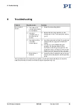
Assignment of the stranded wires and the cable shield
Letter
Wire color
Function
Signal
a
Red
Piezo voltage 0 to 80 V
PIEZO+
b
Black
Piezo voltage ground
PIEZO-
c
---
Exposed cable shield of the motor cable
and the sensor cable
---
d
Yellow
Sensor signal, sine
ENCA+
e
Green
Sensor signal, cosine
ENCB+
f
Red
+5 V supply voltage for sensor
5 V
g
Black
Sensor ground
GND
Requirements
You have read and understood the general notes on installation (p. 17).
The N472B0001 motor / sensor cable (p. 12) is
not
connected to the controller.
Tools and accessories
Suitable vacuum feedthrough
Connection on the air side and on the vacuum side (connector male or female) for the
vacuum feedthrough
N472B0001 motor / sensor cable (p. 12)
Suitable tools for wiring the connections
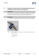
Preparing a VacuumCompatible N472 for Connection to the Controller
1.
Attach the respective connectors for the vacuum feedthrough to the bare stranded
wires of the N-472 cables on the vacuum side and on the air side:
−
Make sure that the stranded wires are assigned to each other as shown in the
connection diagram.
−
Connect the cable shield: The cable shielding from the motor and sensor cable in
the vacuum feedthrough can be routed together to Pin c or the housing.
2.
Check the lines for contacting and short-circuiting using a suitable measuring device.
Содержание N--472 10 Series
Страница 8: ......
Страница 18: ......
Страница 20: ......
Страница 28: ......
Страница 34: ......
Страница 36: ......
Страница 38: ......
Страница 40: ......
Страница 51: ...10 Technical Data N 472 Linear Actuator MP144E Version 1 3 0 47 Figure 18 N 472 21x dimensions travel range...
Страница 53: ...10 Technical Data N 472 Linear Actuator MP144E Version 1 3 0 49 Figure 20 N 472 22x dimensions travel range...
Страница 56: ......