


D84-P06-01 GB R3
21/04/2021
www.photowatt.com
7
used in the system. In addition modules must NOT be
connected together to create a voltage higher than
the maximum permitted system voltage stated on
the module nameplate, even under the worst local
temperature conditions (see Table 1 for the correc-
tion coefficients that apply to open-circuit voltage).
•
A maximum of two strings can be connected in par-
allel without using an over-current protection device
(fuses, etc.) incorporated in series within each string.
Three or more strings can be connected in parallel
if an appropriate and certified over-current protec-
tion device is installed in series with each string. And
it shall be ensured in the PV system design that the
reverse current of any particular string is lower than
the module maximum fuse rating under any circum-
stances.
•
Only modules with similar electrical parameters
should be connected in the same string to avoid or
minimize mismatch effects in arrays.
•
To minimize risk in the event of an indirect lightning
strike, avoid forming loops with the wiring when de-
signing the system.
•
The recommended maximum series fuse rating is
stated on the product's datasheet.
•
Modules should be safely fixed to bear all expected
loads, including wind and snow loads.
•
After the installation of double glass modules, a 30
mm deflection for framed module is allowed.
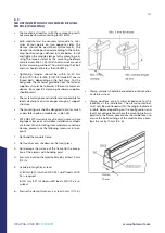
•
For framed modules, a minimum clearance of 6.5
mm (0.25 in) between modules is required to allow
thermal expansion of the frames and modules.
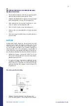
OPTIMUM ORIENTATION AND TILT
•
To maximize the annual yield, please calculate
the optimum orientation and tilt for PV modules in
that specific installation site. The highest yields are
achieved when sunlight shines perpendicularly onto
the PV modules.
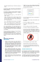
AVOID SHADING
•
Even minor partial shading (e.g. from dirt deposits)
reduces the yield. A module can be considered to be
unshaded if its entire surface is free from shading all
year round. Sunlight should be able to reach at least
the front side of the module even on the shortest day
of the year.
•
For optimizing the power generation of the rear side
of bifacial modules, obstacles between modules and
the mounting ground should be avoided as much as
possible.
•
Constant shading conditions can affect module ser-
vice lifetime, due to accelerated ageing of the en-
capsulation material and thermal stress on the by-
pass diodes.
RELIABLE VENTILATION
•
Bifacial modules use direct, reflected, or diffuse sun-
light on the backside to generate additional pow-
er. Therefore, bifacial modules are not suggested
to be used in building attached photovoltaic sys-
tems (BAPV). If BAPV, or similar mounting is still re-
quired, sufficient clearance of at least 10 cm (3.94
in) between the module and the mounting surface
needs to be provided to allow cooling air to circulate
around the back of the module. This also allows con-
densation or moisture to dissipate.
•
According to UL 1703, if any other specific clearance
required for maintaining a system fire rating should
prevail. Detailed clearance requirements pertaining
to system fire ratings must be provided by your rack-
ing supplier.
5.1
MODULE WIRING
CORRECT WIRING SCHEME
•
Ensure that the wiring is correct before starting up
the system. If the measured open circuit voltage
(Voc) and short-circuit current (Isc) differ substantial-
ly from the specifications, this indicates that there is
a wiring fault.
•
When modules have been pre-installed but the sys-
tem has not been connected to the grid yet, each
module string should be kept under open-circuit
conditions and proper actions should be taken to
avoid dust and moisture penetration inside the con-
nectors.
•
Do not connect different connectors (brand and
model) together.
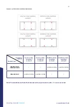
•
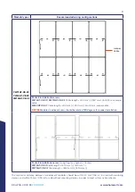
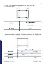
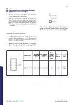
For PW72LHT-CB-XF, PW72HT-CB-XF and PW60HT-
CB-XF modules, EDF ENR PWT offers several cable
length options to match various system configura-
tions, which are shown in table 2:
•
On below figures, bold lines represent cable installa-
tion pathways, while + and - connector correspond to
positive and negative module terminals respectively.
•
Cables should always be fastened on module frames
or mounting rails, in order to avoid shading on mod-
ule rear side.
•
In case where a cable connection method not includ-
ed in below table is used, please confirm suitable ca-
ble length with EDF ENR PWT’s sales representative.


