


D84-P06-01 GB R3
21/04/2021
www.photowatt.com
16
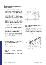
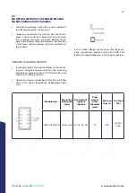
6.3
MOUNTING METHODS FOR FRAMED BIFACIAL
MODULE (SINGLE-AXIS TRACKER)
•
The bolts and clamps used in this section should fol-
low the requirements in 6.1 and 6.2.
•
Under any conditions the junction box cannot be-
come in contact with the subjacent racking structure.
If any racking structures, especially bearing house,
have to be located under the modules, the distance
H the frame and the racking structure should be at
least 40mm.
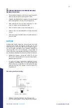
TRACKER 1P BOLTING METHOD
•
Install and tighten the module clamps to the mount-
ing rails using the torque stated by the mounting
hardware manufacturer. M6 X 1 (1/4”) bolt and nut are
used for this bolting method.
•
Tightening torques should be 6~9 Nm (4.5~6.6 ft-lbs)
M6 X 1 (1/4”) coarse thread bolts, depending on bolt
class.
•
If your tracker design cannot meet the above dis-
tance requirement, please contact EDF ENR PWT
technical support department in writing for advices.
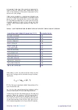
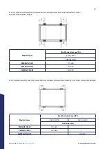
Module type
Mounting
hole space
(mm)
Fixed mount-
ing hole
location
Plain
washer
outer
diameter
(mm)
Distance
H (mm)
Test load
(Pa)
PW72LHT-CB-XF A1-A3: 400 A1, A2, A3, A4
16
<80
+2400/-
2400


