


D84-P06-01 GB R3
21/04/2021
www.photowatt.com
14
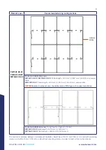
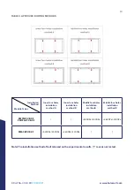
6.2
MOUNTING METHODS FOR FRAMED BIFACIAL
MODULE (CLAMPING)
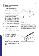
•
The mechanical load test with these mounting meth-
ods were performed according to IEC 61215.
•
Each module must be securely fastened at a mini-
mum of four points on two opposite sides. The
clamps should be positioned symmetrically. The
clamps should be positioned according to the autho-
rized position ranges defined in table below. Install
and tighten the module clamps to the mounting rails
using the torque stated by the mounting hardware
manufacturer. M8 X 1.25 (5/16”) bolt and nut are used
for this clamping method. The yield strength of bolt
and nut should not be less than 450MPa.
•
Tightening torques should be within 16~20 Nm
(11.8~14.75 ft-lbs) for M8 (5/16”-18 Grade B7) coarse
thread bolts, depending on the bolt class. For the
bolt grade, the technical guideline from the fastener
suppliers should be followed. Different recommen-
dations from specific clamping hardware suppliers
should prevail.
•
The system designer and installer are responsible for
load calculations and for proper design of support
structure.
•
The mounting rails shall be designed to limit as much
as possible shade on module rear side cells.
•
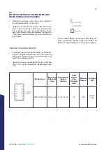
EDF ENR PWT’s warranty may be void in cases where
improper clamps or unsuitable installation methods
are found. When installing inter-modules or end-type
clamps, please take the following measures into ac-
count:
1. Not bend the module frame
2. Not touch or cast shadows on the front glass
3. Not damage the surface of the frame (to the excep-
tion of the clamps with bonding pins)
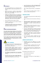
4. Ensure to overlap the module frame by at least 5 mm
(0.2 in)
5. Overlap in length by at least
a) 80 mm (3.15 in) when 2400 Pa < uplift load ≤ 4000
Pa is required
b) 40 mm (1.57 in) when uplift load ≤ 2400 Pa is re-
quired
6. Ensure the clamp thickness is at least 3 mm (0.12 in)
•
Clamp material should be anodized aluminum alloy
or stainless steel.
•
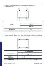
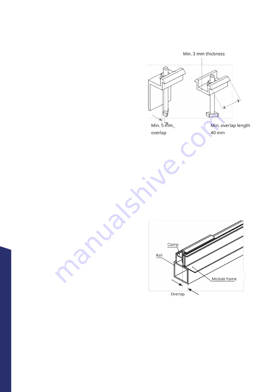
Clamp positions are of crucial importance for the
reliability of the installation. The clamp centerlines
must only be positioned within the ranges indicated
in table below, depending on the configuration and
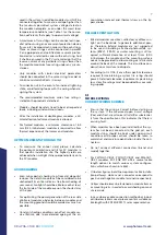
load. For configurations where the mounting rails run
parallel to the frame, precautions should be taken to
ensure the bottom flange of the module frame over-
laps the rail by 10 mm (0.4 in).
10 mm


