


D84-P06-01 GB R3
21/04/2021
www.photowatt.com
5
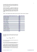
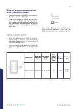
Minimum string fuse rating < X ≤ Maximum string fuse
rating
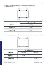
The maximum string fuse ratings can be found on the
product's datasheet for all the certified EDF ENR PWT bi-
facial module types.
The minimum string fuse rating for compliance with NEC:
2017 code and IEC62548: 2016 requirement is suggested
to be determined as follows:
Minimum string fuse rating = Isc
STC
x 1.25 x Max (1.175,
Impp
α
÷ Impp
STC
)
Impp
α
= the highest 3-hour current average resulting
from the simulated local simultaneous irradiances on
the front and rear sides of the PV array accounting for
elevation and orientation
Isc
STC
= the listed short circuit current at 0% bifacial
gain on the PV module datasheet or nameplate label
Impp
STC
= the listed MPP operating current at 0% bifacial
gain on the PV module datasheet or nameplate label
An assembly, together with its overcurrent device (s),
that is listed for continuous operation at 100 percent of
its rating shall be permitted to be used at 100 percent of
its rating, and therefore shall not require the additional
1.25 multiplier.
Electrical calculations and design must be performed by
a competent engineer or consultant.
Please contact EDF ENR PWT’s technical support team
for additional information pertaining to engineering op-
timization and approval of project specific module string
lengths.
4.0
UNPACKING AND STORAGE
PRÉCAUTIONS
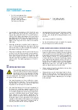
•
Modules should be stored in a dry and ventilated en-
vironment to avoid direct sunlight and moisture. If
modules are stored in an uncontrolled environment,
the storage time should be less than 3 months and
extra precautions should be taken to prevent con-
nectors from being exposed to moisture or sunlight,
like using connector endcaps. Connector endcaps
are available upon request.
•
When unloading module pallets from containers,
please use a fork lift to remove the module pallets
and the forklift should be close to the ground in or-
der to avoid the top of module pallets touching the
top of the cabinet door. The thickness of forklift teeth
should be less than 75mm and the length of the fork-
lift teeth should be more than 2300mm.
•
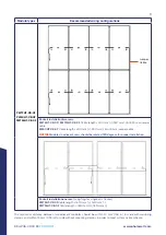
Unpack module pallets carefully, following the steps
shown on the pallet. Unpack, transport and store the
modules with care.
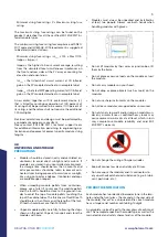
•
Do not lift modules by their wires or junction box, lift
them by the frame.
•
Do not place excessive loads on the module or twist
the module.
•
Do not carry modules on your head.
•
Do not drop or place objects (such as tools) on the
modules.
•
Do not use sharp instruments on the modules.
•
Do not leave modules unsupported or unsecured.
•
Do not stand, step, walk and/or jump on modules un-
der any circumstances. Localized heavy loads may
cause severe micro-cracks at cell level, which in turn
may compromise module reliability and void EDF
ENR PWT’s warranty.
•
Modules must always be unpacked and installed by
at least two people. Always use both hands when
handling modules with gloves.
•
Do not change the wiring of bsypass diodes
•
Keep all connectors clean and dry at all times.
•
Do not expose the modules and its connectors to
any unauthorized chemical substance (e.g. oil, lubri-
cant, pesticide, etc.).
PRODUCT IDENTIFICATION
Each module has two identical barcodes (one in the lami-
nate under the front glass, the second on the rear side of
the module) that act as a unique identifier. Each module
has a unique serial number containing 14 digits.
A nameplate is also affixed to the rear glass of each mod-
ule. This nameplate specifies the model type, as well as the
main electrical and safety characteristics of the module.


