


6 Software
The calibration values of the FPN calibration are not stored with
UserSetSave
(or
CameraHeadStoreDefaults
). Use the command
Correction_SaveToFlash
for this (see
Correction_SaveToFlash
).
6.9
Persistent IP address
It is possible to set a persistent IP address:
1.
Set
GevPersistentIPAddress
(in category
TransportLayerControl
) to the desired IP address.
2.
Set
GevPersistentSubnetMask
(in category
TransportLayerControl
) to the sub net mask.
3.
Set
GevCurrentIPConfigurationPersistent
(in category
TransportLayerControl
) to True.
4.
Set
GevCurrentIPConfigurationDHCP
(in category
TransportLayerControl
) to False.
5.
The selected persistent IP address will be applied after a reboot of the camera.
6.10
PLC Settings
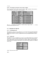
6.10.1
Introduction
The Programmable Logic Controller (PLC) is a powerful tool to generate triggers and software
interrupts. A functional diagram of the PLC tool is shown in Fig. 6.4. THE PLC tool is described
in detail with many examples in the [PLC] manual which is included in the PFInstaller.
The simpliest application of the PLC is to connect a PLC input to a PLC output. The connection
of the ISO_IN0 input to the PLC_Q4 camera trigger is given as an example. The resulting
configuration is shown in Section 6.10.2.
1.
Identify the PLC notation of the desired input in Fig. 6.4. In our example, ISO_IN0 maps to
A0 or Line0.
2.
Select a Signal Routing Block (SRB) that has a connection to the desired PLC input and
connect it to the PLC input. In our example, SRB PLC_I0 will be used as it has a connection
to Line0. To connect the SRB to input, set PLC_I<x> to the input. In the example, set PLC_I0
to Line0.
3.
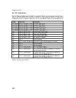
Identify the PLC notation of the desired output. A table of the PLC mapping is given in
Section 5.6. In the example Q4 is the desired output.
4.
Connect the LUT that corresponds to the desired output to the SRB from step 2. In the
example, PLC_Q4 is connected to PLC_I0. ISO_IN0 has an inverter in the I/O decoupling
block, therefore it is better to invert it again in the PLC: set
PLC_Q4_Variable0
to
PLC_I0_Not
.
Note that every LUT has the capability to connect up to 4 inputs. In the example only the
first input (
PLC_Q4_Variable0
) is used. The other inputs are ignored by setting the
PLC_Q4_Variable
to
Zer
o and the
PLC_Q4_Operator
to
Or
for inputs 1 to 3.
5.
If a PLC output is used to connect to a camera trigger, then the corresponding Trigger
Source must be activated. In the example,
TriggerSource
is set to
PLC_Q4
and
TriggerMode
is
set to
On
.
114
Содержание DR1-D1312(IE)-G2
Страница 2: ......
Страница 4: ...2...
Страница 8: ...CONTENTS 6...
Страница 14: ...2 How to get started GigE G2 Figure 2 3 PFInstaller components choice 12...
Страница 60: ...4 Functionality Figure 4 31 Trigger source Figure 4 32 Trigger Inputs Multiple GigE solution 58...
Страница 96: ...4 Functionality 94...
Страница 122: ...6 Software 120...
Страница 128: ...8 Warranty 126...
Страница 130: ...9 References 128...


