13
Copyright © 2013 Alary Design / PhotoShip One LLC -
www.PhotoShipOne.com
RC and Joystick Control Connections
The A10 is cable of being controlled remotely by an RC controller (Futaba, Spektrum, JR, etc) or a wired
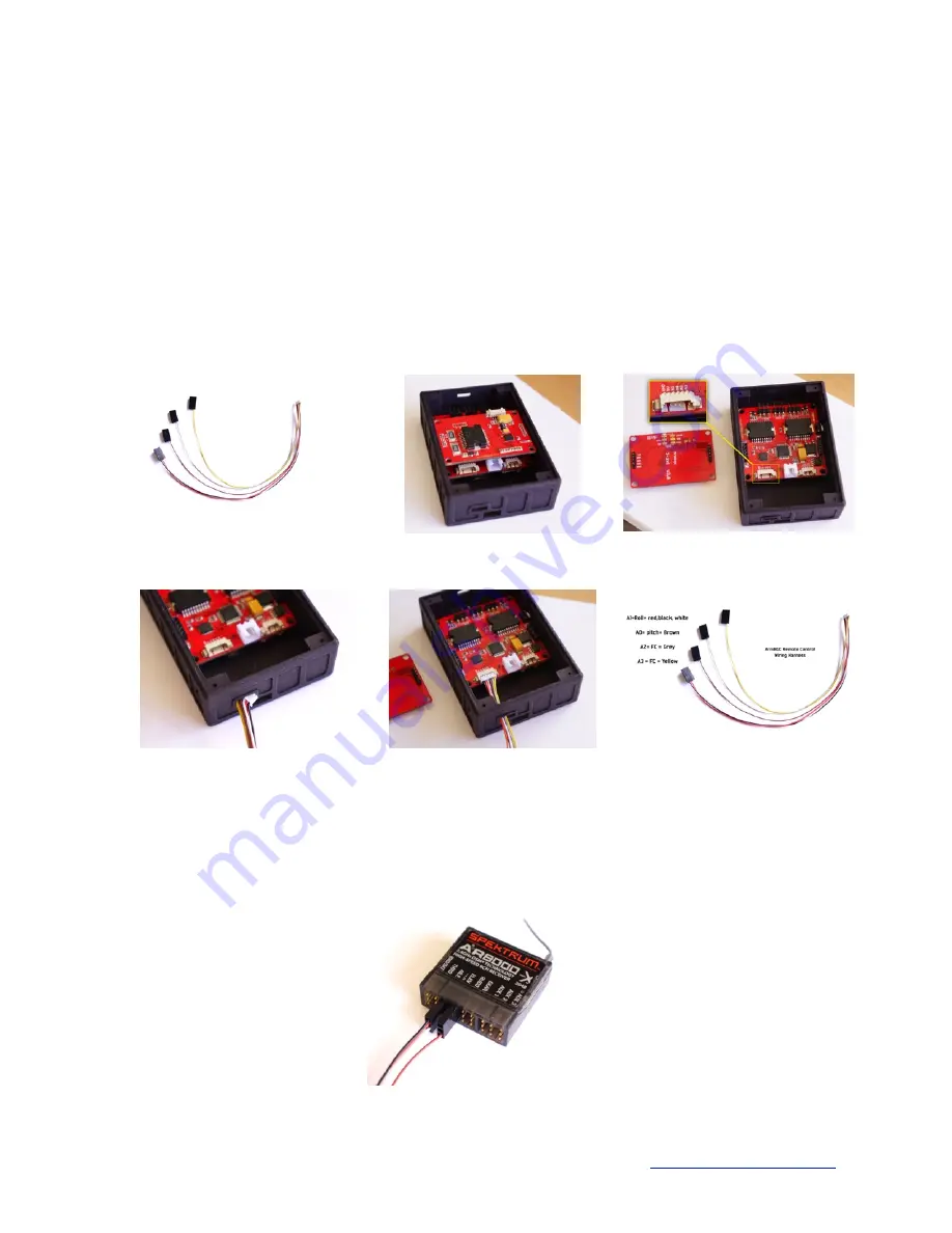
analog joystick. We include the wiring harness for this purpose. Figure 25. To install the harness first
disconnect the motor wires from the controller case. Be sure to remember the orientation of the
connector. It must be plugged back in the same way later. Next, remove the controller case from the A10
by removing the four 2mm screws that hold the case to the case cover plate. Then, carefully pull the case
away from the A10 so that you may access the remote harness port on the controller. The port is located
on the main larger square shaped PCB. Figure 26. To better access the port you may remove the smaller
stacked PCB by carefully prying it loose. Next to the port on the larger PCB you will see the markings
‘Gnd 5v A1 A0 A2 A3’. Figure 27. The wire harness must plug into this port. The harness connector can
be inserted into a rectangular shaped opening in the case next to the USB port. Angle the connector
sideways and it will fit through the opening. Figure 28. Now plug in the harness to the port. When
complete it will look like figure 29. You may now re-attach the smaller PCB and close up the case.
Figure 26. Controller PCBs
Figure 27. Remote Control Port
Figure 28. Wire harness insertion
Figure 29. Controller PCBs
Figure 25. Remote wire harness
Figure 30. Harness Pinout
Now the harness connectors must be plugged into the RC receiver or joystick. Joystick connections are
not covered at this time but will be in a future version of this manual. For RC receiver control connect as
shown. Figure 31. The red/black/white lead is plugged into the roll channel. Brown is plugged in to pitch
channel. Grey and yellow are not used for this purpose.
Figure 31. Connection to RC Receiver


