background image

Instruction Manual

Wingspan : 1630mm (64.2 inch)

Length 

: 1660mm (65.35 inch)

Weight 

: 4500gr – 4800gr

Radio 

: 6 servo hi torque / 4 channel

Engine 

: 120 two stroke

g

Содержание SBACH 120

Страница 1: ...Instruction Manual Wingspan 1630mm 64 2 inch Length 1660mm 65 35 inch Weight 4500gr 4800gr Radio 6 servo hi torque 4 channel Engine 120 two stroke g ...

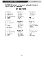
Страница 2: ... CONTENTS THROTTLE CONTROL SYSTEM 1 1 3mm x 500mm wire 1 3 5mm x 350mm nylon pushrod housing 1 Metal connector FUEL TANK 1 Nylon fuel Tank 1 Metal clunk 1 Pre assembled stopper w 3 tube MISCELLANEOUS ITEMS 1 Aluminum dihedral 4 Wing screws 2 4mm x 30mm nylon screws 4 2 6mm x 10mm wood screws 4 Plastic cover 1 Wooden plate 1 Wood box 4 Triangular wooden 1 Spinner 10 2 6mm x 10mm wood screws 2 4mm x...

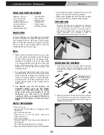
Страница 3: ...neuvers you will need to be throttle conscious that is never apply full throttle on straight and level flying or in dives to prevent flutter SAFETY PRECAUTION This is not a toy Be sure that no other flyers are using your radio frequency Do not smoke near fuel Store fuel in a cool dry place away from children and pets Wear safety glasses The glow plug clip must be securely attached to the glow plug...

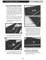
Страница 4: ...uire the use of one 305mm servo extension for each aileron servo One Y harness connector is required and is used to allow the aileron servo to plug into one slot in your receiver You may have a computer radio that allows you to plug the servos into separate slots and then mix them together through the radio transmitter If you choose to mix them with the radio rather than the Y harness refer to the...

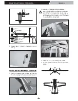
Страница 5: ...ainst the clevis Install the plastic linkball to the servo arm Remember use thread locking compound to secure 1 Locate the pushrod wire Slide a silicon clevis retainer onto a clevis Screw a M3 nut and a threaded metal clevis onto the threaded end of the wire Tighten the nut against the clevis and then install the clevis on the aileron control horn 2 Secure the control horn into the aileron 3 Repea...

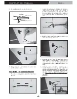
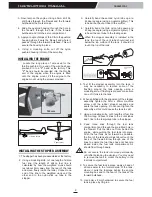
Страница 6: ... remove it cut with only enough pressure to only cut through the covering it s self Cutting into the balsa structure may weaken it This could lead to possible failure during flight 15 16 Plastic screw 3 Attach the wing to the fuselage as picture 4 Test the position of the elevator and adjust it as shown 5 Repeat step 1 step 4 for the second aileron linkage 13 Screw Flat washer Flat washer M3 nut A...

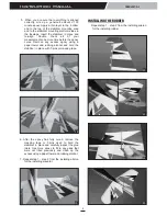
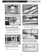
Страница 7: ...nd rubbing alcohol 7 Repeat step 1 step 2 from the installing aileron for the installing elevator 19 5 When you are sure that everything is aligned correctly mix up a generous amount of 30 minute epoxy Apply a thin layer to the bottom and to the top of the stabilizer mounting area and to the stabilizer mounting platform sides in the fuselage Insert the stabilizer in place and re align Double check...

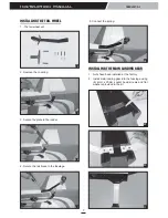
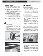
Страница 8: ...Install main landing gear into the fuselage using 4 4mm x 20mm socket head screws and flat washers provided in the kit 29 30 31 28 5 Connect the spring INSTALLING THE TAIL WHEEL 1 The tail wheel set 24 26 27 25 2 Remove the covering 3 Secure the plate to the rudder 4 Secure the tail brace to the fuselage ...

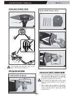
Страница 9: ...gine is equipped with a remote needle valve we suggest installing it into the engine at this time 2 When satisfied with the alignment of the engine use a pencil and mark the mounting hole location onto the firewall where the throttle pushrod will exit After installing the wheel pant apply a small drop of thin C A to the bottom nut Collar 8mm 4mm collar 8mm screw 4mm axle Nut Collar Installing the ...

Страница 10: ...PER ASSEMBLY 1 The stopper has been pre assembled at the factory 2 Using a modeling knife cut one length of silicon fuel line the length of silicon fuel line is calculated by how the weighted clunk should rest about 8mm away from the rear of the tank and move freely inside the tank Connect one end of the line to the weighted clunk and the other end to the nylon pick up tube in the stopper 3 Carefu...

Страница 11: ...ith your radio system INSTALLING THE ELEVATOR SERVO 1 Remove the covering from both size of the fuselage 2 Install two servo to the fuselage as shown Engine side 40 CA glue 38 To muffler To carburator To vent tube 39 170mm 22mm 22mm 10 SBACH Instruction Manual 43 3 The elevator has a block wood plate for mounting the control horn One elevator control horn in positioned on each elevator 41 42 INSTA...

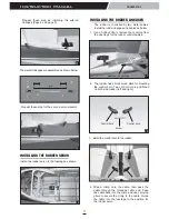
Страница 12: ... to the cable Guide the cable into the fuselage to the position for the rudder servo 2 The rudder has a block wood plate for mounting the control horn Two control horn in positioned on both side rudder left and right 3 Install the control horn to the rudder 48 Control horn Screw Control horn 47 Remove the covering 46 INSTALLING THE RUDDER SERVO Install the rudder servo to the fuselage as shown INS...

Страница 13: ...ain end of the pushrod wire Position the throttle stick and the throttle trim at their lowest positions 4 Manually push the carburator barrel fully closed Angle the arm back about 45 degree from center and attach the servo arm onto the servo With the carburator barrel fully closed tighten the set screw in the adjustable metal connector 5 Remove the excess throttle pushrod wire using wire cutters a...

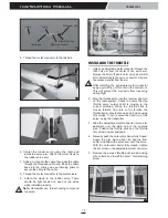
Страница 14: ...INSTALLING THE RECEIVER AND BATTERY 1 Plug the servo leads and the switch lead into the receiver You may want to plug an aileron extension into the receiver to make plugging in the aileron servo lead easier when you are installing the wing Plug the battery pack lead into the switch Secure the cowl 56 MOUNTING THE COWL 1 Remove the muffler and needle valve assembly from the engine Slide the fibergl...

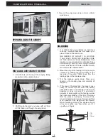
Страница 15: ...PTY 2 Mount the wing to the fuselage Using a couple of pieces of masking tape place them on the top side of the wing 110mm back from the leading edge at the fuselage sides 3 Turn the airplane upside down Place your fingers on the masking tape and carefully lift the plane 4 If the nose of the plane falls the plane is nose heavy To correct this first move the battery pack further back in the fuselag...

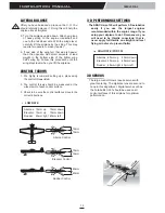
Страница 16: ...nt Digital servos such as the Futaba BLS 351 should be used on all control surfaces of this airplane for optimum performance Aileron Control 15mm 15mm Rudder Control 40mm 40mm Elevator Control 15mm 15mm CONTROL THROWS 1 We highly recommend setting up a plane using the control throws listed 2 The control throws should be measured at the widest point of each control surface 3 Check to be sure the co...

Страница 17: ...cially small children and animals well back from the area of operation This is a flying aircraft which will cause serious injury in case of impact with a person or animal NEVER fly near power lines aerials or other dangerous areas including airports motorways etc NEVER use damaged or deformed propellers or spinners DO NOT dispose of empty fuel containers on a fire this can lead to an explosion NEV...

Страница 18: ...s at the slowest possible speed Switch on the transmitter Switch off the transmitter Check that the transmitter batteries have adequate power Switch off the receiver Switch on the receiver ALWAYS take off into the wind Check that the wings are correctly fitted to the fuselage If the model does not respond correctly to the controls land it as soon as possible and correct the fault Empty the fuel ta...

Отзывы: