background image

MC11 Control Unit 

Installation


66650  6.0 

17 

6.2 

Installation procedure 

Before installing the MC11 control unit, make sure that you are observing all of the safety notices 

found in the "Safety notices to observe during installation" section. 
 

6.2.1 

Mounting the MC11 control unit to the MEGAMAT MLZ drive 


NOTICE 

The installation length of the MEGAMAT MLZ drive should not be less than 291 mm 

(installation length of MEGAMAT MLZ drive together with standard clevis). The drive or 

drive control unit could be mechanically damaged if the installation length is shorter 

than this. 


Figure 9 

Mounting the MC11 control unit 

MEGAMAT MLZ drive (an example) 

Guidance profile 

MC11 control unit 

Guidance groove for the motor casing cover on 

the drive MEGAMAT MLZ 

MC11 control unit attached to the drive 

Fastening screw (3.5 mm x 13 mm) 

Support for guidance profile 


Содержание DewertOkin MC11

Страница 1: ...MC11 Control Unit Installation Instructions Translation of the original installation instructions ...

Страница 2: ......

Страница 3: ...in de Info dewertokin de Creation of a complete operating instruction manual for the entire end product These instructions are only intended to be used by the end product manufacturer They should not be given to the operator of the end product The factual information contained within may be used as a basis when creating the end product manual The warning and danger notices are best suited for use ...

Страница 4: ...ions 6 1 3 Conventions used 6 2 Safety notices 7 2 1 Proper and intended usage 7 2 2 Selection and qualification of personnel 8 2 3 Notice on safety during operations 8 2 4 Product labelling 9 3 Possible combinations 10 3 1 Layout of system connections 10 4 Description 11 4 1 Components 11 5 Technical specifications 14 6 Installation 16 6 1 Safety notices to observe during installation 16 6 2 Inst...

Страница 5: ...ontrol Unit General Information 66650 6 0 5 9 2 Cleaning and care 31 10 Disposal 32 10 1 Packaging material 32 10 2 Components in the control unit 32 EU Declaration of Conformity 33 Additional information 34 ...

Страница 6: ...procedures will help to minimize the risk of accident and injury and damage to the MC11 control unit or the end product These installation instructions have been written with due care and attention However we cannot guarantee that the data images and drawings are complete and correct nor do we accept any liabi lity for the information contained therein unless required by law We reserve the right t...

Страница 7: ...combustible or explosive gases or vapours e g anaest hesiology may be present in the proximity of open fires or other heat sources such as furnaces ovens or di rect sunlight as a power source for toys or games in any application that will be cleaned with an automated washing system in a moist environment or outdoors CAUTION The MC11 control unit may not be operated by by small children by frail or...

Страница 8: ...operations Basic safety rules must be followed in order to ensure that the end product can be continually ope rated in a safe manner These rules must be observed while using the end product and while instal ling the MC11 control unit These rules and safety measures can be categorized as follows Construction measures before the installation refer to the Ensuring operational reliability dur ing inst...

Страница 9: ... unit The ratings plates shown are examples the specifications for MC11 control unit may differ from this illustration Figure 1 Ratings plate example for the MC11 control unit MC11 Model name xxxxx Article number 100V 240V 50 60Hz Input voltage and frequency Max 4 00A Rating of fuse Duty cycle 2 min ON 18 min OFF Intermittent operations 2 minutes 18 minutes Prod date Production date Calendar week ...

Страница 10: ... has separate system instruction manuals containing the additional information and in structions needed for these systems 3 1 Layout of system connections Refer to the sticker on the control unit for details about layout and positioning of the connections The sticker is located above the sockets It indicates the proper type of connections The layout of the connection scheme is individual and depen...

Страница 11: ...d technical changes in the course of our continual product improvement process 4 1 Components The housing of the MC11 control unit has a connection for the power feed in and connections for the drives and handset The connection for the drive handset is fitted with a mechanism to guard against accidental unplugging The MC11 control unit can be plugged into a MEGAMAT MLZ drive Figure 3 Components fo...

Страница 12: ...opriate power cable is included depending on the regional version USA continental Eu rope the UK or Australia WARNING Only use the proper power cable that is permitted in your country Be sure to use the correct plug shape refer to E F Figure 4 Power cord regional variants A MC11 control unit B Power plug USA version C Power plug German version D Power plug Australian version E Power plug United Ki...

Страница 13: ...sed to connect the end product with the grounding conductor on the power supply cord Attach the grounding cable to your application in compliance with all applicable standards and using state of the art methods Figure 5 Grounding cable on the power supply cord of the MC11 control unit A Optional grounding cable B Power cable B A ...

Страница 14: ...d weight Length x width x height 169 mm x 166 mm x 92 mm Weight Approx 770 g Ambient conditions for operation storage and transport Transport storage temperature From 20 C to 50 C From 4 F to 122 F Operating temperature From 10 C to 40 C From 50 F to 104 F Relative humidity From 30 to 75 Air pressure From 800 hPa to 1060 hPa Height 2000 m 1 Mode of operation intermittent duty 2 minutes 18 minutes ...

Страница 15: ...specifications 66650 6 0 15 Figure 6 Dimensions of the MC11 control unit top view in mm Figure 7 Dimensions of the MC11 control unit front view in mm Figure 8 Dimensions of the MC11 control unit side view in mm 92 169 166 166 169 ...

Страница 16: ...d by using the proper construction methods as described below Overheating A thermal monitoring mechanism switches the MC11 control unit off if it overheats CAUTION The MC11 control unit is equipped with a thermal monitoring mechanism that triggers when the unit overheats If the temperature control has triggered remove the control unit from the power supply allow it to rest for 20 to 30 minutes and...

Страница 17: ... the MEGAMAT MLZ drive should not be less than 291 mm installation length of MEGAMAT MLZ drive together with standard clevis The drive or drive control unit could be mechanically damaged if the installation length is shorter than this Figure 9 Mounting the MC11 control unit A MEGAMAT MLZ drive an example B Guidance profile C MC11 control unit D Guidance groove for the motor casing cover on the dri...

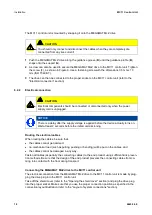
Страница 18: ...voltage is applied before the device actually turns on Wait at least 2 seconds before the initial commissioning Routing the electrical cables When routing the cables be sure that the cables cannot get jammed no mechanical load such as pulling pushing or bending will be put on the cables and the cables cannot be damaged in any way Fasten all cables especially the connecting cables to the end produc...

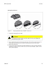
Страница 19: ...y dis connected from any live current 2 Use a suitable tool to press the three locking clips down in the notches as shown in Figure 10 At the same time tilt the shield cover forward so that the clips come out of the notches 3 Remove the shield cover 4 You can now connect or disconnect a plug and socket Be sure to use the proper socket the assignments of plugs to sockets in shown in the connection ...

Страница 20: ...ow these assembly instructions The appropriate power cord is included depending on the regional version USA continental Euro pe the UK Australia or Japan WARNING Only use the proper power cable that is permitted in your country Be sure to use the correct plug shape refer to Figure 11 Connecting the pluggable power cord to the MC11 control unit A MC11 control unit B Snap on cap C Power plug D Power...

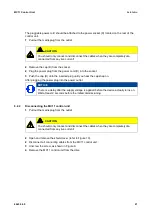
Страница 21: ...ug until you hear the cap snap on After plugging the power plug into the power outlet NOTICE There is a delay after the supply voltage is applied before the device actually turns on Wait at least 2 seconds before the initial commissioning 6 2 4 Disconnecting the MC11 control unit 1 Pull out the mains plug from the outlet CAUTION You should only connect and disconnect the cables when they are compl...

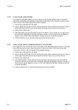
Страница 22: ...ection positions 4 Push the shield cover on until the locking clips snap into the notches 6 2 6 Connecting the optional additional Supervisor or Control Box The Supervisor or the Control Box can be connected to the optional Supervisor socket The sticker above the Supervisor socket shows the position of the socket refer to the Layout of system connections section in the Combination Possibilities Ch...

Страница 23: ...as shown in Figure 12 Mounting to the end product The MC11 control unit is screwed onto the end product by using four screws for the four mounting points e g DIN 7981 screws with 4 8 mm diameter and suitable length of 6 mm plus screw in depth NOTICE Observe the following while mounting to the end product The MC 11 control unit should be mounted so that it lies against its supporting ma terial No m...

Страница 24: ...unit is screwed onto the end product by using four screws for the four mounting points e g DIN 7981 screws with 4 8 mm diameter and suitable length of 6 mm plus screw in depth as shown in Figure 14 The mounting dimensions are shown in Figure 13 Figure 14 Attaching the MC11 control unit to the end product 158 123 5 174 139 5 ...

Страница 25: ...art up After plugging the power plug into the power outlet NOTICE There is a delay after the supply voltage is applied before the device actually turns on Wait at least 2 seconds before the initial commissioning Power on time intermittent operations The MC11 control unit has been designed for intermittent operations Intermittent operation is an operational mode where the drive must pause after a s...

Страница 26: ...y instructions WARNING Only use the proper power cable that is permitted in your country Be sure to use the correct plug shape refer to Reducing the risk of overheating with the thermal monitor CAUTION The MC11 control unit is equipped with a thermal monitoring mechanism that triggers when the unit overheats If the temperature control has triggered remove the control unit from the power supply all...

Страница 27: ...t is possible to shut down the drive or control unit at any time If the optional battery is connected disconnect the battery plug from the socket on the MC11 control unit Avoiding cable damage Be sure that your operating instructions inform the user about the possible cable risks CAUTION The cables particularly the connecting cable should not be run over In order to pre vent injuries or damage to ...

Страница 28: ...w the additional information found in the rechargeable battery information sheet ID No 45564 7 2 2 Optional rechargeable battery with integrated charging circuitry If you have purchased the MC11 with the integrated charging circuitry and external battery then you should note the following Load the battery for at least 24 hours before first use The battery charge status is displayed on the handset ...

Страница 29: ...wer The drive or control unit is defec tive Please contact your supplier or sa les agent The drive is suddenly not capable of move ment The overheating protection or system protection has been trig gered Remove the overload change or remove the load Allow the system to rest for 20 to 30 minutes with the mains power unplugged If this does not resolve the prob lem contact your supplier or distri but...

Страница 30: ...using periodi cally for any signs of damage Check the housing for breaks or cracks At least every six months Look over the plug in connec tions and electrical access points for signs of damage Check that all electrical cables and connections are firmly seated and correctly positioned At least every six months Look over the cables for any signs of damage Check the connecting cables for pinching or ...

Страница 31: ...er Do not allow fluids to penetrate the lighting Damage to the system could result 1 Be sure to unplug the power cord on the MC11 control unit before you begin cleaning it CAUTION For the optional rechargeable battery Disconnect the battery plug from the socket on the MC11 control unit 2 Clean the MC11 control unit with a dry cloth 3 Be sure that you do not damage the connecting cables during the ...

Страница 32: ...nts cables and metal and plastic parts You should observe all corresponding national and regional environmental regulations when disposing of the MC11 control unit The disposal of the product is regulated in Germany by Elektro G internationally by the EU Directi ve 2012 19 EC WEEE or by any applicable national laws and regulations The MC11 control unit should not be disposed of with normal househo...

Страница 33: ...5 EU DELEGIERTE RICHTLINIE EU 2015 863 DER KOMMISSION vom 31 März 2015 zur Änderung von Anhang II der Richtlinie 2011 65 EU des Euro päischen Parlaments und des Rates hinsichtlich der Liste der Stoffe die Beschränkungen unterliegen COMMISSION DELEGATED DIRECTIVE EU 2015 863 of 31 March 2015 amending Annex II to Directive 2011 65 EU of the European Parliament and of the Council as regards the list ...

Страница 34: ...ication IEC EN 60601 1 section 7 1 Labelling general IEC EN 60601 1 section 7 2 Labelling inscriptions IEC EN 60601 1 section 8 Protection against electrical danger leakage currents IEC EN 60601 1 section 11 1 Overheating protection IEC EN 60601 1 section 11 2 Fire prevention IEC EN 60601 1 section 11 3 Design requirements for fire resistant housing IEC EN 60601 1 section 13 Dangerous situations a...

Страница 35: ...g mechanism such as Control box Supervisor IPROXX SE IPROXX or Meditouch IEC EN 60601 2 52 Section 201 9 6 2 1 Noise level 65 dB A IEC EN 60601 2 52 Section 201 11 1 1 Temperature IEC EN 60601 2 52 Section 201 11 6 5 101 Protection against water ingress only for IPX4 IEC EN 60601 2 52 Section 201 11 8 Loss of power e g using a battery rechargeable bat tery depending on customer requirements IEC EN...

Страница 36: ......

Страница 37: ......

Страница 38: ......

Страница 39: ......

Страница 40: ...DewertOkin GmbH Weststrasse 1 Kirchlengern 32278 Germany Tel 49 0 5223 979 0 Fax 49 0 5223 75182 http www dewertokin de Info dewertokin de ID No 66650 ...

Отзывы: