Installation
MC11 Control Unit
22
66650 6.0
6.2.5
Connecting the optional battery
An external rechargeable battery can be connected to the optional battery socket. The sticker
above the sockets shows the position of the battery socket (refer to the "Layout of system connec-
tions" section in the "Combination Possibilities" Chapter).
1
Pull out the mains plug from the outlet.
2
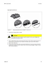
Use a suitable tool to press the three locking clips down into the notches as shown in Figure 10.
At the same time, tilt the shield cover forward so that the clips come out of the notches.
2
Remove the shield cover.
3
Insert the battery plug into the battery socket on the MC11 control unit. Be sure to use the pro-
per socket (the assignments of plugs to sockets in shown in the connection layout diagram).
Figure 2 in the "Combination Possibilities" Chapter shows the connection positions.
4
Push the shield cover on until the locking clips snap into the notches.
6.2.6
Connecting the optional, additional Supervisor or Control Box
The Supervisor or the Control Box can be connected to the optional Supervisor socket. The sticker
above the Supervisor socket shows the position of the socket (refer to the "Layout of system
connections" section in the "Combination Possibilities" Chapter).
1
Pull out the mains plug from the outlet.
2
Use a suitable tool to press the three locking clips down into the notches as shown in Figure 10.
At the same time, tilt the shield cover forward so that the clips come out of the notches.
2
Remove the shield cover.
3
Insert the Supervisor, Control Box or short-circuit plug in the Supervisor socket of the MC11
control unit. Be sure to use the proper socket (the assignments of plugs to sockets in shown in
the connection layout diagram). Figure 2 in the "Combination Possibilities" Chapter shows the
connection positions.
4
Push the shield cover on until the locking clips snap into the notches.


