


Mounting and installing the Gigabit Modular Switch
8042_en_00
PHOENIX CONTACT
1-1
1
Mounting and installing the Gigabit Modular Switch
1.1
Mounting the head station
Mount the head station on a clean DIN rail according to DIN EN 50 022 (e.g., NS 35 ... from
Phoenix Contact). To avoid contact resistance only use clean, corrosion-free DIN rails. Fix
the DIN rail tightly and secure it against twisting to avoid damaging the switch in applications
with a high level of mechanical strain (strong vibrations or shocks). When using "NS 35..."
rails with heavy loads, fix/screw the rails at a distance of about 75 mm.
Before mounting the modules, an end clamp (E/AL-NS 35, Order No. 1201662) should be
mounted on the left-hand side next to the head station to stop the modules from slipping on
the DIN rail. After installation of the modules, install one of the above end clamps to the right
of the station.
Assembly:
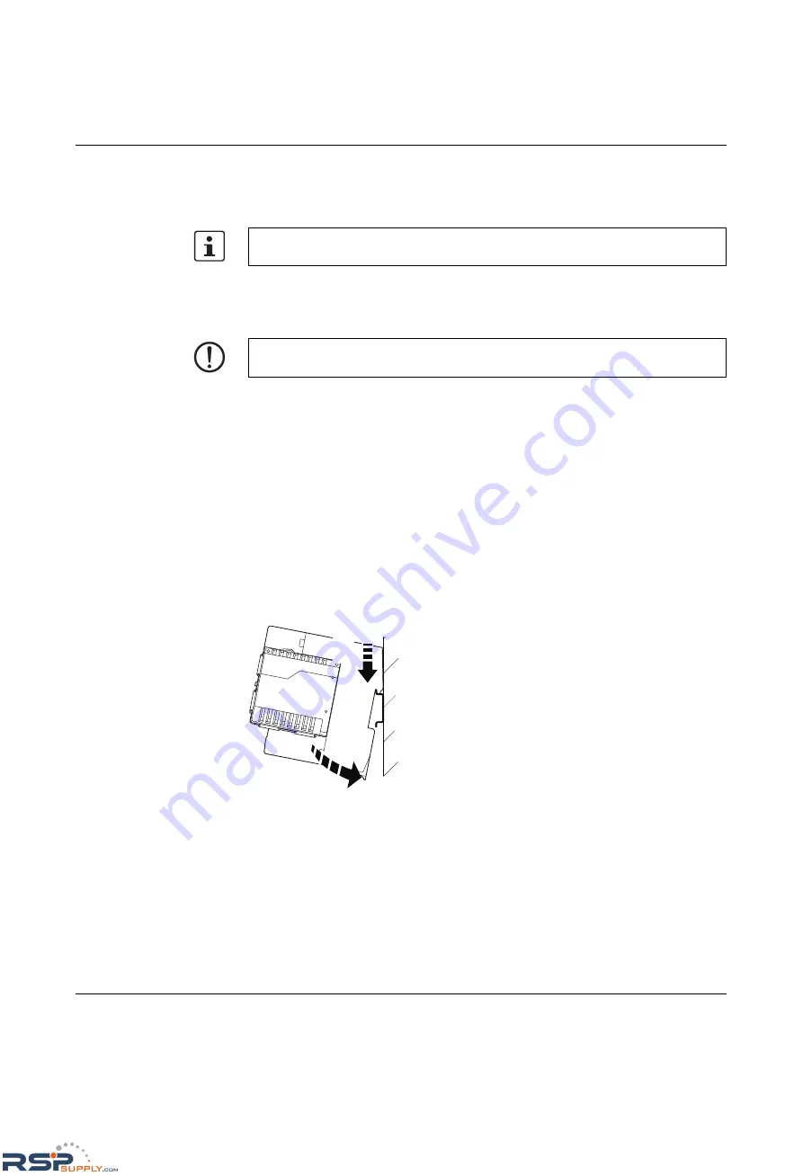
1.
Place the module onto the DIN rail from above (A). The upper holding keyway must be
hooked onto the top edge of the rail. Push the module from the front towards the
mounting surface (B).
Figure 1-1
Snapping the head station onto the DIN rail
2.
Once the module has been snapped on properly, check that it is fixed securely on the
rail. Check whether the positive latches are facing upwards, i.e., snapped on correctly.
Unless otherwise expressly stated, all information provided in this user manual always
applies to both the FL SWITCH GHS 12G/8 and the FL SWITCH GHS 4G/12.
NOTE:
Always switch off the supply voltage when mounting/removing the head station
and extension modules.
B
A
RSPSupply - 1-888-532-2706 - www.RSPSupply.com
http://www.RSPSupply.com/p-14161-Phoenix-Contact-2700271-FL-SWITCH-GHS-4G/12-Modular-Ethernet-Switch.aspx