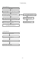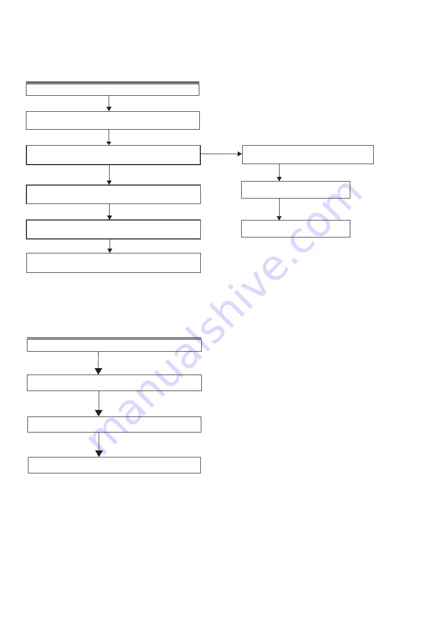
FLOW CHART NO.4
Pass in and out can not read dish sometime.
Check dish if put on the right position or not.
Check dish if cleanlily or not.
Yes
Check & replace a new driver loader .
Yes
Yes
Yes
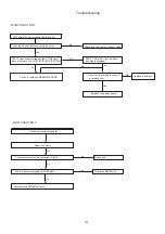
FLOW CHART NO.3
VFD no display
Check VFD display board CN301 whether connection to decoder
board CN1 is
normal
Check VFD display board CN401 whether
connection to KEYS board CN301 is
normal
Check whether VFD board U401 pin 14#\33#\45# has +V5
supply voltage,and the pin 34# whether has -27V supply voltage
Check pin #9,#10,#11(STB,CLK
,
DATA
)
of CN401 in VFD
board to see the signal is normal or not.
No
No
Check the KEYS board location
B301 related electric circuit
Check&replace MCU board
Check&replace a new U401(PT6311)
Test whether VFD board CN401 pin 12#~13# between
has AC5V provide voltage
Yes
Yes
No
Troubleshooting
9-2
Содержание MCM7000/12
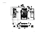
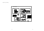
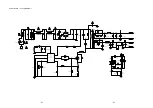
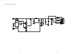
Страница 30: ...AMP BOARD Layout Diagram 12 2 12 2 ...
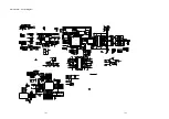
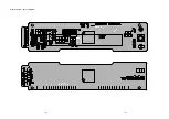
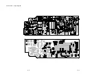
Страница 32: ...Display Board Layout Diagram 12 4 12 4 ...
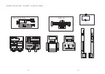
Страница 35: ...Key Board Layout Diagram 12 7 12 7 ...
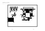
Страница 38: ...T5AH 250V Power Board Layout Diagram 12 10 12 10 ...
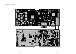
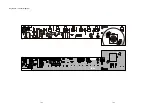
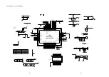
Страница 42: ...Decoder Board Layout Diagram 12 14 12 14 ...
Страница 44: ...Revision List Revision List Version 1 0 Initial Release 14 1 ...

