EN 51
HTS5000W
9.
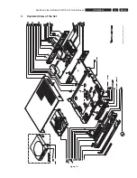
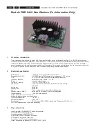
Exploded View & Module PWR 04-01 Non-Wireless
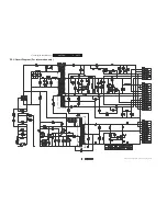
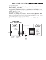
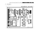
10 Block
diagram
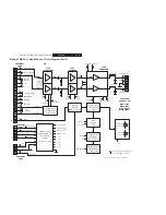
Audio amplifier board 3104 137 00173
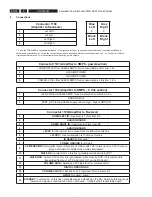
Conn 1100:
Speaker - out
Blue: left +
Black: left -
Grey: right +
Black: right -
1
16
7113
M62429FP
7111
NJM4560
AUDIO LEFT IN
7110
TDA8920B
5100 & 2154
5101 & 2155
4
1
Data & Clock
Levelconverter
7120 & 7121
LED GREEN
6120 & 7106
Mode - level
conditioning
7104
Standby
circuitry
7109, 7101, 7102
Mute
circuitry
7107
Powerdown
detection
7103, 7130, 7131
Powerdown pulse
conditioning
7108, 2194
Power supply
conditioning &
decoupling
circuitry
6113, 6112, 7112
Power Ground
Power Ground
+POWER +27Vdc
+27Vdc
-ANALOG -27Vdc
-POWER -27Vdc
+ 6V
+ 5V
+ 3.3V
+ 15V
- 15V
+6V
+3.3V
___________
POWERDOWN
________
MUTE RX
_________
MUTE DVD
VOL_DATA
VOL_CLOCK
_______
STANDBY
DIGITAL
GROUND
ANALOG
GROUND
ANALOG GROUND
POWER GROUND
+6dB
___________
POWERDOWN
+6V
________
MUTE RX
_________
MUTE DVD
+ANALOG
+6V
+ ANALOG
+ POWER
- ANALOG
- POWER
Connector
1103
Connector
1102
Connector
1101
1
4
1
3
AUDIO RIGHT OUT
AUDIO LEFT OUT
STBY_OUT
F1
AUDIO RIGHT IN
F2
F3
F4
F5
F6
F8
F9
F10
F11
F12
F13
F14
F16
F37
F38
F39
MODE_AMP
F41
F43
F33
VOL_CLOCK
F32
+5V
F34
VOL_DATA
F36
-15Vdc
F35
+15Vdc
F42
F40
F23
F24
F25
F20
+6Vdc
F22
F21
F17 +27Vdc
F18 Power Ground
F19 -27Vdc
LED RED
6121 & 7105
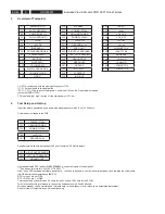
“Fxx “ are testpoints as marked on
the bottomside of the board
+6dB
Attenuator
0 to -83dB
both channels
+30dB
+30dB
Содержание HTS5000W/12
Страница 15: ...EN 15 HTS5000W FTD Display Pin Connection 6 6 FTD Display Pin Connection ...
Страница 16: ...EN 16 HTS5000W Notes 6 FTD Display Pin Connection ...
Страница 40: ...EN 40 HTS5000W Notes Circuit Diagram and PWB Layout 8 ...
Страница 60: ...EN 60 HTS5000W 9 Exploded View Module PWR 04 01 Non Wireless Notes ...

