EN 44
HTS5000W
9.
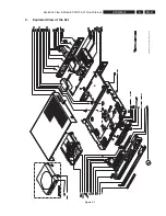
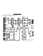
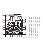
Exploded View & Module PWR 04-01 Non-Wireless
5
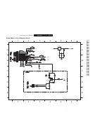
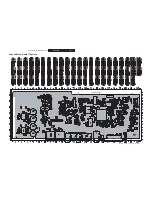
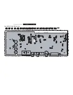
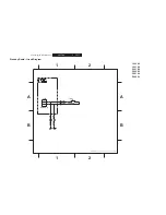
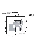
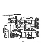
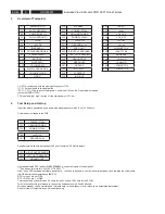
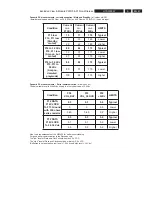
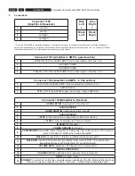
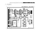
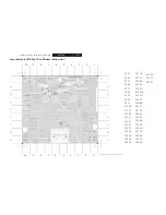
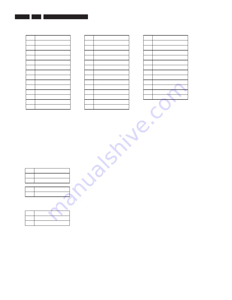
Overview of Testpoints
F1 to F16 correspond with the pinning of connector 1103
*F7, F15 are not used in the application
*F9, F10, F11, F16 are active low signals // see also all info on the Freesystems modules
(document
PRD017002)
F22 is active high ( high = switch off the main /-27Vdc)
6
Test Setup and start up
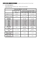
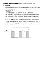
Input signals are generated by an audio sine-signal generator with Z_out < 600 ohms.
Power supply voltages to the PCB:
F17
+POWER (27Vdc)
F18
GROUND POWER
F19
-POWER (-27Vdc)
F20
+6VDC IN
F21
GROUND 6Vdc
Speaker outputs should be loaded with 6 ohm / minimum 50 Watt resistors.
F23
RIGHT OUT SPEAKER
F24
LEFT OUT SPEAKER
F25
GROUND OUT
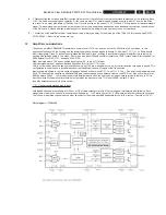
Use the dedicated PSS testtool
3104 137 00231
to control all inputs of the ampli
fi
er.
*** See annex for more info on 3104 137 00231 ****
Also, the by PSS developed software (serial data – tool) has to be used to control the serial data and clock towards the volumechip.
(via DB9 serial cable towards any IBM PC)
DTR = clock = pin 4 of DB9
RTS = DATA = pin 7 of DB9
This testtool has on board loads 50 ohms for the 6Vdc and 100 ohms for the 3.3Vdc.
Two cinch connectors are forseen to connect an audiosource with Zout<600ohms
Mute and standby can be simulated on this testboard. ( with switches or with relay’s to an automated testsystem)
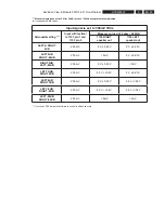
See overview of testpoints for better understanding.
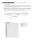
F1
AUDIO LEFT IN
F2
AUDIO GROUND
F3
AUDIO RIGHT IN
F4
AUDIO GROUND
F5
+6VDC
F6
+3.3VDC
F7
ID SEARCH *
F8
POWER GROUND RX
F9
POWERDOWN *
F10
MUTE RX *
F11
MUTE DVD *
F12
VOLUME DATA
F13
DIGITAL GROUND RX
F14
VOLUME CLOCK
F15
GPIO4 *
F16
STANDBY *
F17
+POWER (27Vdc)
F18
GROUND POWER
F19
-POWER (-27Vdc)
F20
+6VDC IN
F21
GROUND 6Vdc
F22
STBY_OUT
F23
RIGHT OUT SPEAKER
F24
LEFT OUT SPEAKER
F25
GROUND OUT
F26
GREEN LED
F27
RED LED
F28
MUTE ALL
F29
6V DETECT
F30
IN RIGHT
F31
IN LEFT
F32
+5Vdc
F33
VOL_CLK
F34
VOL_DAT
F35
+15Vdc
F36
-15Vdc
F37
IN RIGHT TDA
F38
IN LEFT TDA
F39
MODE AMP
F40
- ANALOG
F41
+ ANALOG
F42
- POWER TDA
F43
+ POWER TDA
Содержание HTS5000W/12
Страница 15: ...EN 15 HTS5000W FTD Display Pin Connection 6 6 FTD Display Pin Connection ...
Страница 16: ...EN 16 HTS5000W Notes 6 FTD Display Pin Connection ...
Страница 40: ...EN 40 HTS5000W Notes Circuit Diagram and PWB Layout 8 ...
Страница 60: ...EN 60 HTS5000W 9 Exploded View Module PWR 04 01 Non Wireless Notes ...

