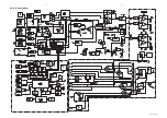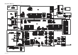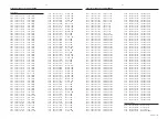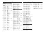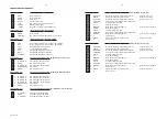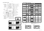
KEY-CDC BOARD - COMPONENT LAYOUT
KEY-CDC BOARD - CHIP LAYOUT
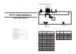
KEY-CDC PART - CIRCUIT DIAGRAM
HEADPHONE PART - CIRCUIT DIAGRAM
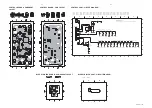
HEADPHONE BOARD - COMPONENT
LAYOUT
HEADPHONE BOARD - CHIP LAYOUT
KARAOKE PART - CIRCUIT DIAGRAM
KARAOKE BOARD - COMPONENT
LAYOUT
KARAOKE BOARD - CHIP LAYOUT
6-4
6-4
6-4
SPR 00 0125
1
2
1
2
A
B
C
A
B
C
1500 B2
1501 A2
1502 B1
2500 A2
2501 A2
2502 A1
2503 A2
2504 A2
5500 A2
5501 B1
5502 B1
9500 A2
22n
2502
1
2
3
4
5
6
a
a
100n
2504
1501
1
FE-BT-VK-N
1502
TC38
9
8
7
1
2
3
4
5
6
2u2
5502
1500
# 9500
5501
2u2
2u2
5500
# 2501
22n
2503
100n
22n
2500
L
Lhp
DPL_SW
R
Rhp
GNDa
# : Provision
Note : Some values may varies, see respective
parts list for correct value.
3139 118 53120...87110 for...3424 pt3 dd wk0035
3139 113 3424 pt3 dd wk0035
This assembly drawing shows a summary of all possible versions.
For components used in a specific version see schematic diagram and respective parts list.
3139 113 3424 pt3 dd wk0035
This assembly drawing shows a summary of all possible versions.
For components used in a specific version see schematic diagram and respective parts list.
Some location on this board is prepared for both 0603 & 0805 SMDs footprint,
in such locations 0603 SMDs may be substituted.
1
2
3
4
1
2
3
4
A
B
A
B
26 B4
1600 B1
2600 B1
2601 B2
2602 A2
2603 B2
2604 B2
2605 B3
2606 B3
2607 A4
2608 A4
3602 A2
3603 B2
3604 A2
3605 B2
3606 B3
3607 A3
3608 B3
4601
a
3609 A3
3610 B4
4600 B4
4601 B4
4605 A1
5600 A1
7600 B
2
7601 A
3
3610
10u
2608
DIPMATE
26
1
2
3
a
a
Mic
a
47u
2602
2605
470n
Mic
4600
470n
2604
8
7
1
2
3
4
5
6
2601
220n
20K
3606
2
13
1600
TC38
9
a
+12A
1K2
3609
560R
3608
+12A
BC847B
7601
2u2
5600
3605
120R
a
1M
3604
3K9
7600
BC847B
3603
4605
100K
10u
2607
3602
100R
2600
22n
1n
2606
2603
1n
1M
3607
+12A
Note : Some values may varies, see respective parts list for correct value.
3139 118 53120...87100 for...3424 pt3 dd wk0035
This assembly drawing shows a summary of all possible versions.
For components used in a specific version see schematic diagram
and respective parts list.
3139 113 3424 pt3 dd wk0035
This assembly drawing shows a summary of all possible versions.
For components used in a specific version see schematic diagram
and respective parts list.
3139 113 3424 pt3 dd wk0035
Some location on this board is prepared for both 0603 & 0805 SMDs
footprint, in such locations 0603 SMDs may be substituted.
6100 A1
6102 A2
6101 A1
1104 B2
1105 B2
2100 B1
3100 A1
3101 A1
3102 A2
3103 B1
3104 B1
3105 B2
3106 B2
3107 B2
GND-B
1
2
3
1
2
3
A
B
A
B
1100 A3
1101 B1
1102 B1
1103 B2
GND-B
120R
3102
6102
120R
3101
6101
120R
3100
6100
3139 118 53120...86950 for...3424 pt3 dd wk0035
GND-B
GND-B
GND-B
1
101
GND-B GND-B
1
102
3104
4K7
10K
3103
2100
100p
1
105
3107
1K2
1
104
1K8
3106
3105
2K7
1
103
3
4
5
6
FE-ST-VK-N
1100
1
2
Cdc2Lit
Cdc1Lit
GND
Cdc3Lit
Note : Some values may varies, see respective parts list for correct value.
This assembly drawing shows a summary of all possible versions. For components used in a specific version see schematic diagram and respective parts list.
3139 113 3424 pt3 dd wk0035
This assembly drawing shows a summary of all possible versions. For components used in a specific version see schematic diagram and respective parts list.
3139 113 3424 pt3 dd wk0035
Some location on this board is prepared for both 0603 & 0805 SMDs footprint, in such locations 0603 SMDs may be substituted.
Содержание FW-P900
Страница 20: ...D O N O T P R I N T B L A N K P A G E ...
Страница 25: ...4 1 4 1 SET BLOCK DIAGRAM PCS 103 615 Blue Strip wOOx BassTreble ...
Страница 44: ...PCS 103 378 9 6 9 6 COMPONENT LAYOUT CHIP LAYOUT 3 4 2 1 6 5 3 4 2 1 6 5 ...
Страница 55: ...10 3 CS 53 302 Service Position ...
Страница 56: ...10 4 CS 53 303 Wiring ...
Страница 74: ...D O N O T P R I N T B L A N K P A G E ...
Страница 101: ...14 1 14 1 SPR 00 0142 ...


