3-2
3-2
SPR 00 0119
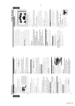
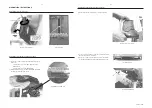
Dismantling of the ETF Tape Module
1) Remove 6 screws G as indicated to loosen the ETF Tape
Module (pos 1103).
Dismantling of Rear Portion
AF Board Top View
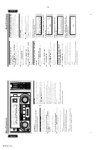
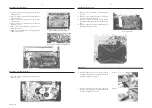
Dismantling of the Front Board
1) Uncatch C as indicated to loosen the Dolby Pro logic
Board (pos 1108).
2) Remove 1 screw D as indicated to loosen the Headphone
Board (pos 1100-E).
3) Remove 5 screws E as indicated to loosen the Plate
Front (pos 254).
4) Remove 4 screws F as indicated to loosen the Front
Board (pos 1100-A).
5) Remove 5 screws H as indicated to loosen the Control
Board (pos 1100-B).
6) Remove 1 screw Q as indicated to loosen the Blue Strip
LED Board (pos 1100-F).
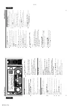
1) The Knob Volume Rotary (pos 149) can be remove by
inserting a strong string into the slot and pull it out in the
direction as indicated. See picture 1.
2) The Knob Jog Rotary (pos 138) can be remove by
inserting a strong string into the slot and pull it out in the
direction as indicated. See picture 2.
Picture 1
Picture 2
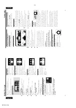
Repair Hints
1) Remove 5 screws J as indicated to loosen the AF Board
(pos 1101).
2) Remove 4 screws K and uncatch M1 as indicated to
loosen the Tuner Board (pos 1102).
3) Remove 3 screws L and 1 screw N (if obstructed) and
uncatch M2 as indicated to take out the Plate Rear (pos
234).
4) Remove 2 screws P to free the Power Module (pos 1105)
from the Bottom Plate assembly.
Remove Control and Blue Strip LED Boards
Remove Dolby Pro logic (DPL) Board
Содержание FW-P900
Страница 20: ...D O N O T P R I N T B L A N K P A G E ...
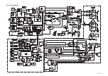
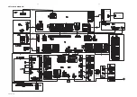
Страница 25: ...4 1 4 1 SET BLOCK DIAGRAM PCS 103 615 Blue Strip wOOx BassTreble ...
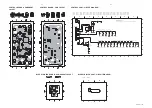
Страница 44: ...PCS 103 378 9 6 9 6 COMPONENT LAYOUT CHIP LAYOUT 3 4 2 1 6 5 3 4 2 1 6 5 ...
Страница 55: ...10 3 CS 53 302 Service Position ...
Страница 56: ...10 4 CS 53 303 Wiring ...
Страница 74: ...D O N O T P R I N T B L A N K P A G E ...
Страница 101: ...14 1 14 1 SPR 00 0142 ...


