Service Modes, Error Codes, and Fault Finding
EN 18
FHP PDP
5.
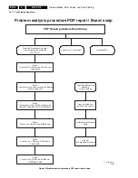
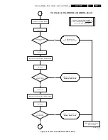
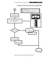
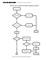
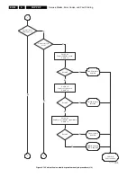
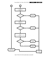
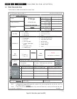
Figure 5-8 5V Vcc check ABUSR, ABUSL, Y-Sus X-Sus board
Set is disconnected from AC mains!
Connect CN42 ABUSR
Switch the PSU on
Vcc 5V OK?
I < 0.35A?
Switch off the PSU
Connect CN52 ABUSL
Switch on the PSU
Vcc 5V OK?
I < 0.35A?
Switch off the PSU
Connect CN23 X-Sus
Switch on the PSU
Vcc 5V OK?
I < 2A?
Switch off the PSU
Connect CN33 Y-Sus
Switch on the PSU
Vcc 5V OK?
I < 2A?
Switch off the external PSU
and disconnect.
Remove ADM 1 - 8
ABUSR board is defective.
Replace ABUSR board
ABUSL board is defective.
Replace ABUSL Board
X-Sus board is defective
Replace X-Sus board
Y-Sus board is defective
Replace Y-Sus board
Switch PSU off
End of analysis
Y
Y
Y
Y
N
N
N
N
3
4
In the next steps the 5V Vcc power supply lines will be checked.
AExternal Power Supply is connected to D6224/D6225 5V Vcc on the set PS.
For testing each board, ramp up the External PSU from 0 to 5V.
Monitor the current!
Logic buffer circuit has abnormalty.
Logic buffer circuit has abnormalty.
DC/DC power supply circuit or control
logic circuit has abnormality
DC/DC power supply circuit or control
logic circuit has abnormality
5V Vcc check ABUSR, ABUSL, Y-Sus, X-Sus board
Adjust External PSU
max. current to 2A
E_14580_012.eps
101005

