Service Modes, Error Codes, and Fault Finding
EN 15
FHP PDP
5.
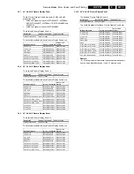
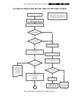
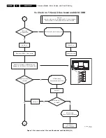
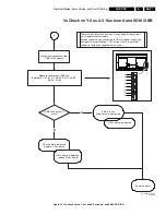
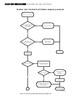
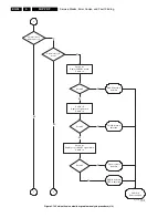
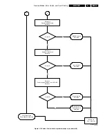
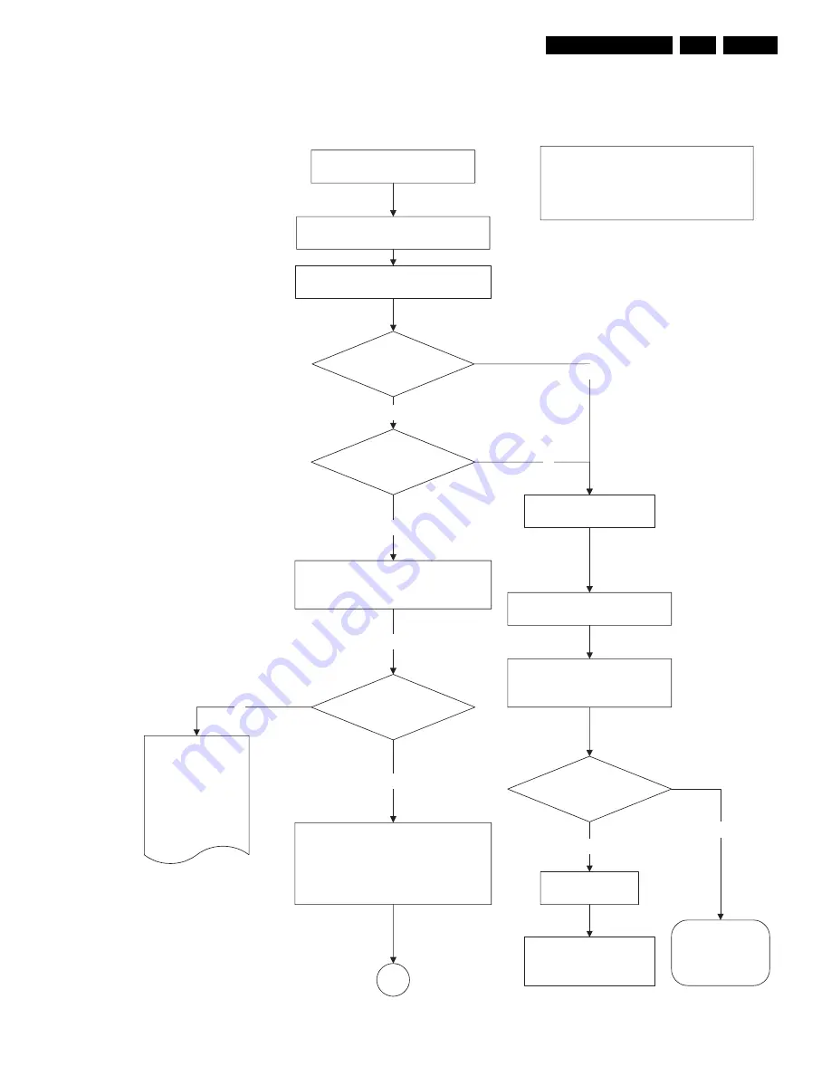
Figure 5-5 Problem analysis procedure the entire screen does not light
The entire screen does not light
Disconnect CN306 Logic board
Standby LED is on?
Set is in Standby?
All the boards are connected
Connect the set to mains.
Disconnect the mains plug.
Remove the following power connections
CN23 X-Sus
CN33 Y-Sus
CN42 ABUSR
CN52 ABUSL
Set is going into protection?
3.3V Standby is ok.
Switch on the set via RC
N
Switch the set on via vacation switch
Switch vacation switch off
Check 3.3V Stby
on pin 1 CN6
Logic board
N
Caution: never disconnect connectors or
remove boards when the mains plug is connected.
Allow discharge of power supplies before
disconnecting connectors!
Switch vacation switch on and check
3.3V Stby on PSU
3.3V Stby
on pin 1 Cn306
is ok?
Defect is on PSU
board.
Standby supply repair
See PSU repair
method
CC on Logic board
Y
N
Y
Y
Y
Y
1
Check supply voltages
Vcc pin 6 Cn306
Vs pin 10 Cn323
Va pin 1 Cn323
Vcc Pin 3 Cn323
Vcc pin 7 Cn342
Vcc pin 7 Cn352
N
Replace Logic Board
Follow Logic board
replacement procedure
Problem Analysis Procedure the entire screen does not light.
E_14580_009.eps
101005


