Page 94
9. 16-Bit Timer/Counter2 (TC2)
9.2 Control
T
5CL8
9.2 Control
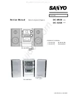
The timer/counter 2 is controlled by a timer/counter 2 control register (TC2CR) and a 16-bit timer register 2
(TC2DR).
Note 1: fc: High-frequency clock [Hz], fs: Low-frequency clock [Hz], *: Don't care
Note 2: When writing to the Timer Register 2 (TC2DR), always write to the lower side (TC2DRL) and then the upper side
(TC2DRH) in that order. Writing to only the lower side (TC2DRL) or the upper side (TC2DRH) has no effect.
Note 3: The timer register 2 (TC2DR) uses the value previously set in it for coincidence detection until data is written to the upper
side (TC2DRH) after writing data to the lower side (TC2DRL).
Note 4: Set the mode and source clock when the TC2 stops (TC2S = 0).
Note 5: Values to be loaded to the timer register must satisfy the following condition.
TC2DR > 1 (TC2DR
15
to TC2DR
11
> 1 at warm up)
Note 6: If a read instruction is executed for TC2CR, read data of bit 7, 6 and 1 are unstable.
Note 7: The high-frequency clock (fc) canbe selected only when the time mode at SLOW2 mode is selected.
Note 8: On entering STOP mode, the TC2 start control (TC2S) is cleared to "0" automatically. So, the timer stops. Once the STOP
mode has been released, to start using the timer counter, set TC2S again.
TC2DR
(0025H,
0024H)
15
14
13
12
11
10
9
8
7
6
5
4
3
2
1
0
TC2DRH (0025H)
TC2DRL (0024H)
(Initial value: 1111 1111 1111 1111)
R/W
TC2CR
(0023H)
7
6
5
4
3
2
1
0
TC2S
TC2CK
TC2M
(Initial value: **00 00*0)
TC2S
TC2 start control
0:Stop and counter clear
1:Start
R/W
TC2CK
TC2 source clock select
Unit : [Hz]
NORMAL1/2, IDLE1/2 mode
Divider
SLOW1/2
mode
SLEEP1/2
mode
R/W
DV7CK = 0
DV7CK = 1
000
fc/2
23
fs/2
15
DV21
fs/2
15
fs/2
15
001
fc/2
13
fs/2
5
DV11
fs/2
5
fs/2
5
010
fc/2
8
fc/2
8
DV6
–
–
011
fc/2
3
fc/2
3
DV1
–
–
100
–
–
–
fc (Note7)
–
101
fs
fs
–
–
–
110
Reserved
External clock (TC2 pin input)
111
TC2M
TC2 operating mode
select
0:Timer/event counter mode
1:Window mode
R/W
Содержание CEM2100/00
Страница 2: ...2 ...
Страница 3: ...BLOCK DIAGRAM ...
Страница 4: ...WIRING DIAGRAM 4 ...
Страница 5: ...CIRCUIT DIAGRAM MAIN BOARD 5 ...
Страница 6: ...6 ...
Страница 7: ......
Страница 11: ...PCB LAYOUT MAIN BOARD TOP SIDE VIEW 11 ...
Страница 12: ...PCB LAYOUT MAIN BOARD BOTTOM SIDE VIEW 12 ...
Страница 13: ...PCB LAYOUT PANEL BOARD TOP SIDE VIEW ...
Страница 14: ...14 PCB LAYOUT PANEL BOARD BOTTOM SIDE VIEW ...
Страница 15: ...PCB LAYOUT REMOTE BOARD TOP SIDE VIEW 15 ...
Страница 16: ...PCB LAYOUT REMOTE BOARD BOTTOM SIDE VIEW 16 ...
Страница 17: ...PCB LAYOUT TUNER BOARD TOP SIDE VIEW 17 ...
Страница 18: ...PCB LAYOUT TUNER BOARD BOTTOM SIDE VIEW 18 ...
Страница 19: ...PCB LAYOUT SD BOARD TOP SIDE VIEW ...
Страница 20: ...20 PCB LAYOUT CD CONNECTOR TOP SIDE VIEW ...
Страница 21: ...PCB LAYOUT ISO BOARD BOTTOM SIDE VIEW 21 ...
Страница 22: ...22 SET EXPLODER VIEW DRAWING ...
Страница 23: ...1 of 2 CEM2100 Trouble shooting Trouble shooting Trouble shooting Trouble shooting ...
Страница 33: ...7 0 6SHFLILFDWLRQ 6 VWHP EORFN GLDJUDP ...
Страница 110: ...7 0 6SHFLILFDWLRQ 5HYLVLRQ KLVWRU 2 2 s u 2 u 2 7 t 2 2 2 S S 5 2 v 2 2 ...
Страница 111: ...8 Bit Microcontroller TLCS 870 C Series T5CL8 ...
Страница 113: ...Revision History Date Revision 2008 7 31 1 First Release ...
Страница 114: ......
Страница 122: ...viii ...
Страница 126: ...Page 4 1 3 Block Diagram T5CL8 1 3 Block Diagram Figure 1 2 Block Diagram ...
Страница 130: ...Page 8 1 4 Pin Names and Functions T5CL8 ...
Страница 155: ...Page 33 T5CL8 ...
Страница 156: ...Page 34 2 Operational Description 2 3 Reset Circuit T5CL8 ...
Страница 186: ...Page 64 5 I O Ports 5 8 Port P7 P77 to P70 T5CL8 ...
Страница 194: ...Page 72 6 Watchdog Timer WDT 6 3 Address Trap T5CL8 ...
Страница 214: ...Page 92 8 16 Bit TimerCounter 1 TC1 8 3 Function T5CL8 ...
Страница 270: ...Page 148 12 Asynchronous Serial interface UART1 12 9 Status Flag T5CL8 ...
Страница 280: ...Page 158 13 Asynchronous Serial interface UART2 13 9 Status Flag T5CL8 ...
Страница 332: ...Page 210 16 Serial Bus Interface I2C Bus Ver D SBI 16 6 Data Transfer of I2C Bus T5CL8 ...
Страница 342: ...Page 220 17 10 bit AD Converter ADC 17 6 Precautions about AD Converter T5CL8 ...
Страница 354: ...Page 232 19 Flash Memory 19 4 Access to the Flash Memory Area T5CL8 ...
Страница 388: ...Page 266 21 Input Output Circuit 21 2 Input Output Ports T5CL8 ...
Страница 397: ...Page 275 T5CL8 23 Package Dimensions LQFP64 P 1010 0 50D Rev 01 Unit mm ...
Страница 398: ...Page 276 23 Package Dimensions T5CL8 ...
Страница 400: ......
Страница 403: ...TC94B14MFG 2010 01 12 3 Pin Layout and Block Diagram Top View Pin Layout Top View TC94B14MFG Top View TEST1 ...
Страница 428: ...TC94B14MFG 2010 01 12 28 Package LQFP80 P 1212 0 50F Weight 0 6 g Typical ...