Fault Finding and Repair Tips
GB 8
A10PTV2.0 NTSC
5.
5.3
Service Alignment Mode (SAM)
5.3.1
Introduction
The Service Alignment Mode (SAM) is used to align the set
and/or adjust the option settings and to display/clear the error
code buffer values.
Entering Service Alignment Mode
To enter the Service Alignment Mode (SAM), press the
following key sequence on the remote control transmitter:
0-6-2-5-9-6-INDEX or status.
Do not allow the display to time out between entries while
keying the sequence
It is also possible to enter the Service Alignment Mode by
pressing the “” and “VOLUME -” key on the local
keyboard simultaneously for at least 4 seconds when the set
is in SDM.
5.3.2
Exit SAM:
To exit the Service Alignment Mode, press the Power button.
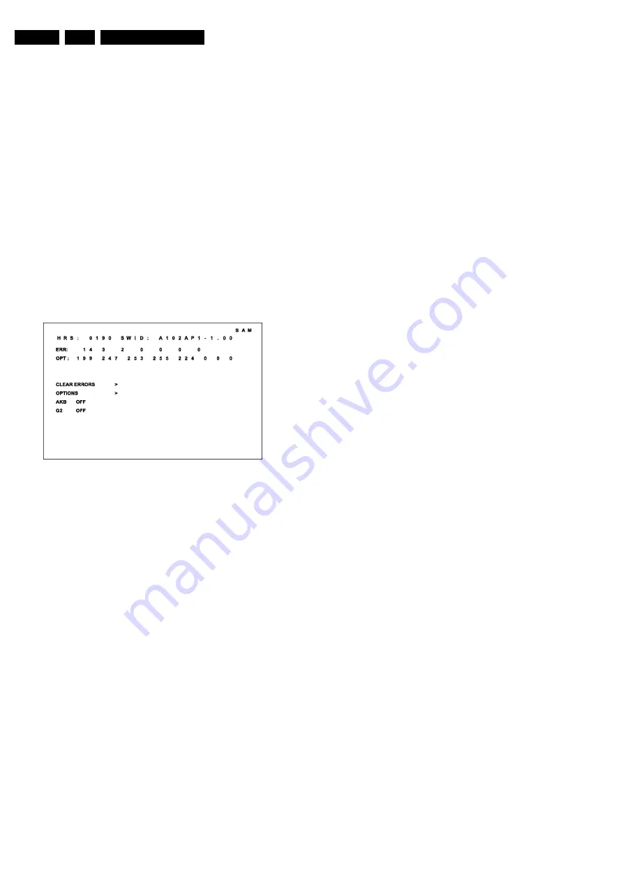
In SAM the following information is displayed on the screen:
Figure 5-2
5.3.3
Explanation Notes/References:
1. Operation Hours (Run Timer):
•
This display indicates the accumulated total of
operational hours. (Shown in hexadecimal format)
2. Software identification of the main micro controller
(A101US1-2.06)
•
A10 is the engineering chassis name for the A10
PTV chassis
•
1US1 is a character combination to indicate the
software type and the supported languages: 3AP1 or
3AP2 are also possible in the Asian Pacific Region.
•
US = United States, AP = Asia Pacific
•
1 = Main Software language version number
•
2.06 = sub-version number
3. Error buffer (7 errors possible):
•
Displays the 7 most recent errors. The most recent
error is displayed at the upper left.
4. Option bytes (8 codes possible):
•
Summary of options is explained below.
5. Sub menus are listed in a scroll menu.
5.3.4
SAM Menu Control
Menu items may be selected using the cursor UP/DOWN
keys.
•
The selected item will be highlighted.
•
When not all menu items will fit on the screen, pressing
the cursor UP/DOWN keys on the remote transmitter will
display the next/previous menu items.
With the cursor LEFT/RIGHT keys, it is possible to:
•
(de)activate the selected menu item (e.g. GEOMETRY)
•
change the value of the selected menu item ( e.g. VER-
SLOPE )
•
activate the selected submenu (e.g. SERV-BLK)
Access to Normal User Menu
Pressing the “MENU” button on the remote control switches
between the SAM and the normal user menus (with the SAM
mode still active in the background). Pressing the “MENU”
key in a submenu will return the screen to the previous menu.
5.4
The Menus and Submenus
5.4.1
Clear Errors
Erases the contents of the error buffer. Select the CLEAR
ERRORS menu item and press the cursor LEFT or cursor
RIGHT key. The contents of the error buffer are cleared.
The functionality of the OPTIONS and ALIGNMENTS
(TUNER, WHITE TONE, GEOMETRY, SOUND, and
SMART SETTING) submenus are described in the service
adjustments.
5.4.2
Error Code Buffer and Error Codes
Explanation of the Error Code Buffer
The error code buffer contains all errors detected since the
last time the buffer was erased. The buffer is written from left
to right. When an error occurs that is not yet in the error code
buffer, the error code will appear at the left side and all other
errors shift one position to the right.
The error code buffer will be cleared in the following cases:
•
by activating CLEAR ERRORS in SAM menu
•
exiting SDM or SAM with the “Standby" command on the
remote control
•
upon automatic reset when content has not changed for
50 consecutive hours
By leaving SDM or SAM via the power switch, the error buffer
will not be reset.
Examples:
ERROR: 0 0 0 0 0 0 0 :No errors detected
ERROR: 6 0 0 0 0 0 0 :Error code 6 is the last and only
detected error
ERROR: 9 6 0 0 0 0 0 :Error code 6 was first detected and
error code 9 is the last detected (newest) error
The contents of the error buffer can also be displayed by use
of the “blinking LED” procedure, if no picture is available. See
explanation of “The blinking LED procedure “below.
5.4.3
Error Code Definition
In case of non-intermittent faults, clear the error buffer before
starting the repair, to make sure “old” error codes are not
present. If possible check the entire content of the error
buffers. In some situations an error code is only the result of
another error code (and not the actual cause).
Note: a fault in the protection detection circuitry can also lead
to a protection.
Error codes 1,2, 3, and 4 are protection codes, and in this
case the supplies of some circuits will be switched off. Also
in protection, the LED will blink the number of times
equivalent to the most recent error code.
CL 16532052_003.eps
090501


