Circuit Description
GB 92
A10PTV2.0 NTSC
9.
Figure 9-14
Figure 9-15
9.7.2
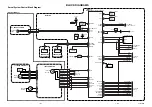
SVM Circuit
Luminance drive from the SSB panel is fed to the SVM panel
via connector via 1804, Pin 3. The signal is amplified by
Q751 and Q753. The coil L752 and Capacitor C755 makes
up a differentiation circuit to detect light to dark and dark to
light transitions. The detected signal is fed to a Power
Amplifier, which drives SVM Yokes on each of the CRT’s.
This drive speeds up the pulse during luminance transitions
to sharpen the edges, increasing picture sharpness. Fast
Blanking is fed to transistor Q755 to blank drive to the SVM
amplifier for areas of the screen where On Screen Display is
present. This panel is powered by the 15 and 130-volt
sources.
CL 06532143_021.eps
081100
CL 06532143_022.eps
081100


