


14
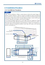
3.5 Installation Procedure
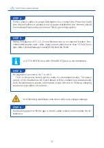
STEP 1.
Build 1020mm x430mm x 200mm concrete base on the level to stand charger in
advance; implant Φ80 mm conduit for input AC and Ethernet cables and implant
4 pcs of M12 screw stick out the concrete base for 40 mm to fix the charger. The
positioning of these 4 pcs of M12 screws should be within ± 2 mm in short axis,
± 8 mm in long axis according to screw holes of charger.
To fit this positioning requirement, a steel plate fixture be suggested. Please
create the fixture by the following drawing or order this fixture from your vendor.
The other way to fix the charger on concrete base is install 2 of L-brackets ac
-
cessories outside of charger and drill the screw holes (Φ12 mm) on the cement
base as drawing below.
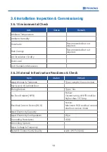
60cm
*The distance should be more than
60cm from the wall
AC Cable
Conduit
Ø
80mm
4 x M12 screw stick
(L Bracket orifice)
4 x
Ø
12
(L Bracket orifice)
844
250
1020
430
278
215
88
90
636
210
192
11
0
200
Ø80mm
(AC Cable Conduit)
4 x Ø12
(L Bracket orifice)
4 x M12
screw stick
3.5.1 Installation Procedure
(Front Direction)
Содержание DC EVSE 60KW
Страница 2: ......
Страница 10: ...2 5 Direction of cooling Airflow Air Out Air In 7 ...
Страница 15: ...Remove these 4 pcs of fixing M12 screws STEP 3 12 ...
Страница 55: ...52 NOTE ...
Страница 56: ...NOTE ...
Страница 57: ...NOTE ...
Страница 58: ...Manufacturer Contact Info Sticker www phihong com tw ...