PFT 00260621 Скачать руководство пользователя страница 39

Mixing pump G 4 X FU 230/400V / Part 2 Overview, operation and service

Operation

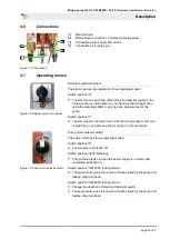
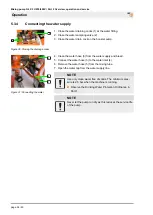
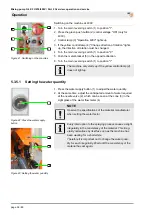
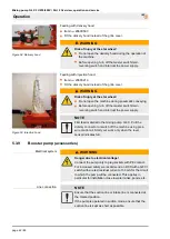
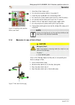
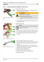
5.3.5.2 Watering the mixing zone

3

2

1

Figure 44: Watering the mixing zone
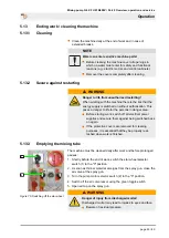
NOTE

The pump must generally be flushed with water. Flushing

with water makes it easier for the pump to start up.

1. Connect the water hose (1) to the mixing tube.
2. Remove the blind cover (2) from the lower water nozzle.
3. Press and hold the water supply button (3) until water emerges

from the lower water nozzle.

4. Screw the blind cover (2) back on the lower water nozzle.

5.3.6

Mortar hoses

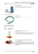
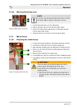
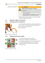
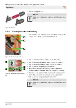
5.3.6.1 Preparing the mortar hoses

3

1

2

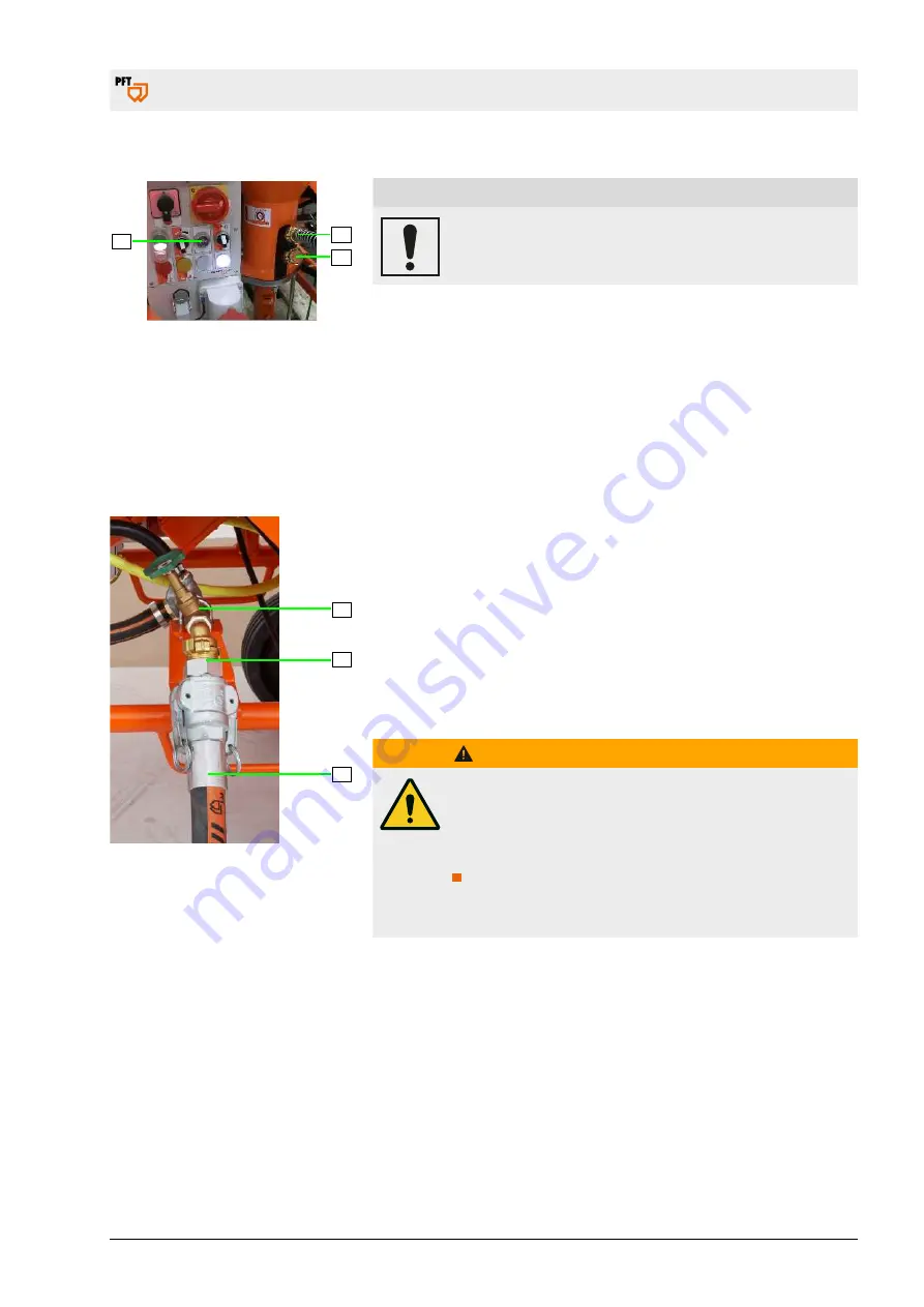
Figure 45: Preparing the mortar hose

1. Connect the cleaner coupling (1) at the water extraction valve (2).
2. Connect the mortar hose (3) to the cleaner coupling (2).
3. Open the water sampling valve (2) and water the mortar hose (3).
4. Remove mortar hose and cleaner coupling again and disconnect

from each other.

5. Remove all the water from the mortar hose.
6. Pre-lubricate the mortar hose with about 2 litres of wallpaper paste.
7. The wallpaper paste is mixed through the mortar hose with the first

mixing.

WARNING

The mix could burst out under pressure and result in

serious injuries, especially injuries to the eyes.
Hoses that tear off can lash wildly and injure those

standing nearby!

Never loosen the hose couplings as long as there is

pressure on the mortar hoses (check mortar pressure

gauge)!

page 39 / 80

Содержание 00260621

Страница 1: ...230 400V 1 3 Ph 50 Hz with AVO 500 Item no 00260621 G 4 FC 230 400V 1 3 Ph 50 Hz without booster pump with accessories Item no 00422135 G 4 FC 230 400V 1 3 Ph 50 Hz without booster pump Item no 00423...

Страница 2: ...oduction of this document exploitation or communication of its contents are prohibited unless expressly autho rised Violations may lead to damage compensation All rights are reserved in the event of p...

Страница 3: ...ater manifold 23 4 5 5 Air compressor 24 4 5 6 Mortar pressure gauge 24 4 6 Connections 25 4 7 Operating modes 25 4 8 Voltage 230V 400V changing 26 4 9 Pressure booster pump 26 4 10 Accessories 27 5 O...

Страница 4: ...63 6 Maintenance 67 6 1 Safety 67 6 1 1 Remove connection cable 68 6 2 Environmental protection 68 6 3 Maintenance plan 69 6 4 Maintenance work 69 6 4 1 Implementation by a service techni cian 69 6 4...

Страница 5: ...are for presentation purposes of facts not necessarily to scale and may slightly differ from the actual model of the device 1 2 Division The operating manual is divided into 2 books Part 1 Safety dri...

Страница 6: ...escribed Warning Death or serious injury may occur if you do not take the precautions described Caution Minor injury may occur if you do not take the precautions described Note Property damage may occ...

Страница 7: ...00 14 EC Internal production control as per article 14 paragraph 2 in connection with annex V This declaration only refers to the machine in the state in which it has been placed on the market Parts s...

Страница 8: ...al non flammable gases Maximum operating pressure initial pressure 16 bar After pressure infinitely adjustable from 1 5 to 6 bar Smallest possible initial pressure 2 5 bar Minimum pressure gradient in...

Страница 9: ...nly use the flowmeter as intended Always adhere to the usage directives of the material manufacturer Strictly follow all instructions in this operating manual We accept no responsibility for damages c...

Страница 10: ...echnically perfect condition as well as for its intended use and while taking into account the safety and hazard information in the operating manual In particular faults that can impair safety must be...

Страница 11: ...only in rooms where the hazard of a potentially explosive atmosphere is not given 1 8 5 3 Hot surfaces on the air compressor General information WARNING Risk of injury due to hot surface Surface tempe...

Страница 12: ...il Value Unit Empty weight approx 308 kg Length 1200 mm Width 720 mm Height 1530 mm Individual weights Detail Value Unit Pump motor with tilt flange 51 kg Mixing pump 81 kg Material hopper 162 kg Air...

Страница 13: ...kW 3 3 A Q6 Water connection Detail Value Unit Operating pressure minimum 2 5 bar Connection inch 2 3 Operating conditions Environment Detail Value Unit Temperature range 2 45 C Relative humidity max...

Страница 14: ...pump output Detail Value Unit Pump capacity approx 17 l min at 385 rpm Operating pressure maximum 20 bar Maximum grain size 2 mm Feed range max with 25 mm 15 m Feed range max with 35 mm 20 m Referenc...

Страница 15: ...is danger to life from falling parts or uncontrolled swinging parts Therefore Never step under suspended loads Observe the instructions regarding the provided anchorage points Do not attach to project...

Страница 16: ...accordance with the transport conditions to be expected Only environmentally friendly materials were used for the packaging The packaging should protect the individual components until the assembly f...

Страница 17: ...ght possibly observe eccentric centre of gravity 3 5 Transport in van Figure 6 Transport 1 Remove the water hose from the mixing tube 2 Loosen the locking lever and lift the mixing tube 3 Insert the h...

Страница 18: ...ies to face and eyes can occur Therefore Before opening the couplings ensure that there is no more pressure on the hoses observe display at mortar manometer Carry out the following steps before beginn...

Страница 19: ...Pump motor 2 Motor protection handle 3 Deflector plate 4 Protective grille with sack opener 5 Material hopper 6 Air compressor 7 Carrying handle 8 Double stop castor 9 Water sampling valve 10 Pressure...

Страница 20: ...4 X with 230V AC or 400V three phase drive was specially developed for pumping spraying and applying dry mortar pasty materials for machine use and much more up to 2 mm grain size The pump output can...

Страница 21: ...wns and excessive wear on pump motor mixing shaft and pump always use orig inal PFT spare parts such as PFT rotors PFT stators PFT mixing shaft PFT mortar hoses These are compatible with each other an...

Страница 22: ...y connector connection for remote control 8 Yellow control lamp wrong direction of rotation 9 Red control lamp motor protection switch activated 10 Pushbutton for control voltage ON OFF 11 Pump motor...

Страница 23: ...th motor 1 Pump motor 6 05 kW 2 Mixing tube with rubber mixing section 3 SD 6 3 SLIMLINE pump unit 4 5 4 Water manifold 5 1 2 3 4 8 7 6 Figure 14 Water tap assembly 1 Water flow meter 150 1 500l h 2 P...

Страница 24: ...casing and sophisticated filter system Changing filter insert for motor cooling air easy access from the outside and easy replacement The actual intake air for the compressor is taken in via two inter...

Страница 25: ...or carrying out a pressure test of the pump Switch position 1 The star wheel is running in sync with the mixing pump motor and is switched on and off using the air control or remote control Figure 19...

Страница 26: ...Change voltage 1 Turn the main switch to position 0 2 Open the control cabinet door 3 Switch the voltage switch 1 to 230V or 400V 4 Close the control cabinet door 5 Turn the main reversing switch to...

Страница 27: ...4 10 Accessories Injection hood for G 4 RITMO XL HM 24 Item no 20600213 The PFT injection hood is used for feeding dry material to the mixing pump using the PFT SILOMAT pneumatic conveying system Deli...

Страница 28: ...mixing of the material Direct drive via tang of the rotor Contents approx 1 2 l ROTOQUIRL II cpl with size 35 coupling Item no 20118400 Remixer for better decomposition and mixing of the material Dire...

Страница 29: ...fety socket coupling 32A 5 pin 400 V 3 Ph Item no 00226538 Extension cable 5 x 4 mm RED 5 32 A 25 m 400 V 3 Ph Item no 20423920 Extension cable 5 x 4 mm RED 5 32 A 50 m 400 V 3 Ph Item no 20423900 You...

Страница 30: ...s according to the instruc tions in this user manual Prior to starting your work ensure that all components are complete and undamaged Prior to starting your work ensure that all covers and protection...

Страница 31: ...n NOTE The machine operator or the person working in the dusty area always has to wear a dust protection mask when filling the machine The rules of the Committee on Dangerous Substances AGS can be fou...

Страница 32: ...rmissible operating pressure of at least 40 bar The burst pressure of the mortar hose must reach at least 2 5 times the value of the operating pressure 5 2 Inspection by machine operator Prior to each...

Страница 33: ...e machine 2 Put up the machine on a stable even surface and secure against unwanted movements Do not tilt or roll the machine away Place the machine where it cannot be hit by any falling objects The c...

Страница 34: ...e operation of the machine make sure that the adapter cable is connected on the mains side and not on the machine side NOTE Check extension cables and adapters for damage and ensure function before st...

Страница 35: ...speed can be controlled via the poten tiometer Disadvantage As the machine is controlled via the frequency converter the gear motor no longer reaches its full capacity maximum 4 kW 5 3 3 3 Connecting...

Страница 36: ...ump 5 4 3 Figure 37 Connecting the water 4 Clean the water hose 3 from the water supply and bleed 5 Connect the water hose 3 to the water inlet 4 6 Remove the water hose 5 from the mixing tube 7 Open...

Страница 37: ...93686 The connected pressure booster pump ensures the required water pressure of at least 2 5 bar NOTE When working with water from the barrel the inlet strainer must be fitted with a filter screen it...

Страница 38: ...lamp 4 does not light up 5 3 5 1 Setting the water quantity 1 Figure 42 Press the water supply button 2 3 4 Figure 43 Setting the water quantity 1 Press the water supply button 1 to adjust the water...

Страница 39: ...45 Preparing the mortar hose 1 Connect the cleaner coupling 1 at the water extraction valve 2 2 Connect the mortar hose 3 to the cleaner coupling 2 3 Open the water sampling valve 2 and water the mort...

Страница 40: ...hoses do not kink 3 Carefully secure risers so that they do not tear away from their own weight 3 Figure 47 Switching on 4 Turn the pump motor selector switch 3 to right position 5 Allow the machine...

Страница 41: ...hing on the air compressor 1 Switch on the air compressor using the green toggle switch 1 2 As soon as the air compressor has built up pressure in the pipeline system it switches off using the pressur...

Страница 42: ...e master switch main reversing switch and interrupt the power supply NOTE First feed material to the mixing pump G 4 X Pull the dummy connector or switch off the machine using pres sure control air St...

Страница 43: ...best if the suction flange is also filled at that time 5 3 9 2 Putting the pressure booster pump into operation 1 2 Figure 55 Connect lines The following instructions have to be observed before operat...

Страница 44: ...till air in the pump and this has to be completely vented again The suction line has a leak and the pump draws air The suction side screen is clogged There is a kink in the suction hose The maximum su...

Страница 45: ...unctional 5 5 Putting the machine into operation 5 5 1 Checking the mortar consistency Figure 57 Consistency inspection tube 1 Connect consistency inspection tube to the mortar pressure gauge 2 Place...

Страница 46: ...3 The G 4 X can be switched on or off using the remote control 5 7 Applying mortar WARNING Danger of injury from discharged mortar Discharged mortar may lead to injuries to eyes and face Never look i...

Страница 47: ...be sprayed we recommend application on wall surfaces from top to bottom Uniform mixing and spraying cannot be ensured if the amount of water is insufficient This can clog the hoses and the pumping co...

Страница 48: ...to be observed regarding breaks 1 Figure 64 Closing the air tap 1 Close the air tap 1 if the work is interrupted for an extended period of time 2 Figure 65 Switching off the machine 2 Turn the pump mo...

Страница 49: ...to the 0 position 2 Turn the main reversing switch 2 to position 0 5 11 Action in case of power failure Figure 68 Turn the main reversing switch to the 0 position Turn the main reversing switch to th...

Страница 50: ...ed mortar may lead to injuries to eyes and face Never look into the spray gun Always wear protective goggles Always position yourself in such a way that you are not hit by the mortar being discharged...

Страница 51: ...ector switch 5 to right position 8 The machine starts again as soon as the air tap at the spray gun is re opened NOTE In case of a longer power cut the machine and the mortar hoses have to be cleaned...

Страница 52: ...manifold dry 2 Turn the star wheel selector switch 4 to the 0 position 3 Turn the booster pump selector switch 5 to the 0 position 4 Turn the pump motor selector switch 6 to the 0 position 5 Turn the...

Страница 53: ...danger area Before starting work switch off all electrical power supplies and secure them against being switched back on again If the protective covers are removed for cleaning purposes it is essenti...

Страница 54: ...ar hoses and spray gun must be cleaned imme diately at the end of work 1 Connect the cleaner coupling 1 at the water extraction valve 2 2 Press the water saturated sponge ball 3 into the mortar hose 4...

Страница 55: ...otor tilt flange and tilt the motor 2 Remove the mixing shaft 1 and clean it 5 13 6 1 Inserting the mixing tube cleaner 1 2 Figure 81 Inserting the mixing tube cleaner 1 Take the mixing tube cleaner 1...

Страница 56: ...h 5 to right position 5 Allow the machine to run for approx 5 10 seconds until the mixing tube is cleaned 6 Turn the pump motor selector switch 5 to the 0 position 7 Turn the main reversing switch 3 t...

Страница 57: ...se 1 from the mixing tube 2 Undo nuts 2 3 Remove pump unit 3 with pressure flange 4 and mortar pres sure gauge and clean NOTE Only store assembled pumps rotor in stator for a few days since longer sto...

Страница 58: ...t 5 14 1 Safety Personnel The work for rectification of faults described here can be carried out by the operator unless marked otherwise Some works must be carried out only by specially trained skille...

Страница 59: ...Figure 88 Fault displays The following installation indicates faults Pos Light signal Description 1 Red control lamp Lights up on motor protection switch fault Check the motor protection switch 2 Yell...

Страница 60: ...t current Fuse defective Change fuse Service technician Insufficient drop in pressure in the remote control due to blocked air duct or air nozzle pipe Clean blocked air duct or air nozzle pipe Operato...

Страница 61: ...et or replace air pressure safety switch Service technician Compressed air hose or gaskets defective Replace compressed air hose replace gaskets or check compressor Service technician Air tap on spray...

Страница 62: ...vice technician During opera tion water rises in the mixing tube Hose blockage due to mortar being too thick high pressure due to low water factor Remedy hose blockage increase water factor Service te...

Страница 63: ...rticularly to the eyes Persons commissioned with the cleaning of clogged hoses have to wear personal protective equipment protective goggles gloves for safety reasons and must position themselves in s...

Страница 64: ...auge has dropped to 0 bar 10 Turn the pump motor selector switch 4 to the 0 position 11 Turn the main reversing switch 1 to position 0 5 14 6 2 Blockage cannot be cleared 2 1 Figure 91 Check and relie...

Страница 65: ...1 Turn the main reversing switch 1 to position I 2 Press the green pushbutton 2 control voltage ON 3 Switch on the air compressor using the green toggle switch 4 Turn the booster pump selector switch...

Страница 66: ...pump selector switch 4 to the AUTO position 6 Turn the star wheel selector switch 5 to the 1 position 7 Turn the pump motor selector switch 6 to right position 8 Let the machine run for a short while...

Страница 67: ...vere injuries or considerable property damage Prior to starting the works ensure that there is enough space to carry out the works Ensure order and safety at the assembly site Unat tached components o...

Страница 68: ...ing WARNING Danger to life from unauthorised restarting When working with the tool there is the risk that the energy supply is switched on without authorisation This poses a danger to life for the per...

Страница 69: ...n replace filter of compressor Service technician Monthly Clean replace plastic screen in strainer Operator Monthly Clean replace the strainer screen in the pressure reducer Service technician 6 4 Mai...

Страница 70: ...iner 1 2 Figure 97 Plastic screen Implementation by operator 1 Remove the closure cap 1 from the strainer 2 Take out the plastic screen 2 from the strainer monthly 3 Clean the screen 4 Replace the scr...

Страница 71: ...h air 1 Machine switches ON Machine switches OFF Air 0 9 bar 1 2 bar 6 4 7 Setting value pressure switch air compressor Air compressor switches ON Air compressor switches OFF Compressor 2 5 bar 3 1 ba...

Страница 72: ...ection Construction machinery has to be inspected for safe working condition in accordance with the operating conditions and the oper ational requirements as needed however at least once a year by an...

Страница 73: ...p G 4 X FU 230 400V Part 2 Overview operation and service Maintenance 6 8 1 Accessories Recommended accessories equipment can be found in the PFT machine and equipment catalogue or under www pft net p...

Страница 74: ...fore Prior to starting the works ensure that there is suffi cient space Carefully handle components with sharp edges Ensure order and cleanliness at the working place Loose components and tools on top...

Страница 75: ...ble work safety and environmental protection regula tions Prior to starting the disassembly Switch off device and secure against restarting Disconnect the entire energy supply from the machine and dis...

Страница 76: ...spose of remaining components sorted according to the type of material NOTE Environmental damage due to incorrect disposal Electrical scrap and components lubricants and other process materials are su...

Страница 77: ...Mixing pump G 4 X FU 230 400V Part 2 Overview operation and service Disposal page 77 80...

Страница 78: ...Mixing pump G 4 X FU 230 400V Part 2 Overview operation and service Disposal page 78 80...

Страница 79: ...Mixing pump G 4 X FU 230 400V Part 2 Overview operation and service Disposal page 79 80...

Страница 80: ...S AT YOUR SITE Knauf PFT GmbH Co KG Postfach 60 97343 Iphofen Einersheimer Stra e 53 97346 Iphofen Germany Telephone 49 9323 31 760 Fax 49 9323 31 770 Technical hotline 49 9323 31 1818 info pft net ww...

Отзывы: