N
L1
M
3
L2
L3
F1 - F3
K1
10
11
AC 220 ... 240 V
Us
F4
U
V W
S1
S2
k1
K1
H1
S3
2)
A1
A2
T1
T2
Y2
Y1
24
21
22
14
12
11
2)
2)
1)
1)
1)
T1...T3
3)
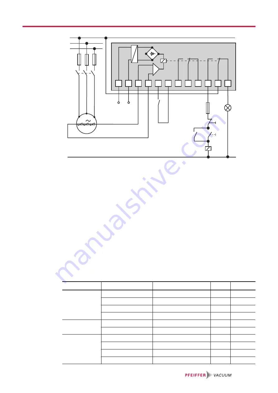
Fig. 13:
Connection example with PTC thermistor tripping unit
U
S
Control voltage
T1 – T3
PTC resistor sensor
S
1
OFF button
H1
Tripping indicator
S
2
ON button
M
Motor, 3-phase
S
3
RESET button
1)
For devices with two relay outputs only
K1
Contactor
2)
For MSR type only
F1 – F4
Fuses
3)
Only for order no.: P 4768 051 FQ
Connecting the PTC thermistor tripping unit
► Route the connection so that the direction of rotation indicated on the pump is maintained, regard-
less of the representation in the circuit diagram.
Motor protection switch
Protection switches with slow tripping characteristics are suitable. The drive motor can have a power
input greater than the rated current I
N
. In accordance with EN 60034-1, 1.5 times the rated current is
permissible for a duration of 2 minutes. The setting should enable the overload capability of the motor,
and be taken from the following tables.
Voltage [V]
Frequency [Hz]
Motor rating [kW]
I
N
[A]
I
max
[A]
230
400
265
460
50
1.1
4.3
31
50
1.1
2.5
18
60
1.3
4.2
31
60
1.3
2.45
18
220
380
60
1.3
4.82
31
60
1.3
2.78
18
200
400
200
400
50
1.5
7.3
49
50
1.5
3.65
28
60
1.5
7.3
63
60
1.5
3.65
35
Installation
23/66
Содержание DUO 35
Страница 1: ...OPERATING INSTRUCTIONS EN Original UNO 35 65 DUO 35 65 Rotary Vane Pump ...
Страница 2: ...PK0168BEN_Q PK0168 2018 01 31 ...
Страница 65: ...65 66 ...
Страница 66: ... PK0168 ed Q Date 1801 P N PK0168BEN ...


