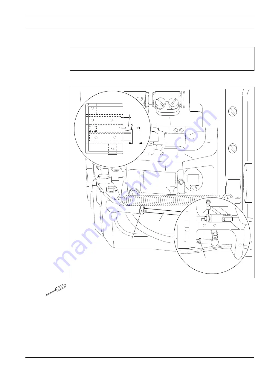
Pfaff 3801-11/071 Скачать руководство пользователя страница 101

Adjustment

13 - 38

Fig. 13 - 35

4

7 mm

2

1

3

13

.06.03

Thread catcher position with respect to needle

Requirement

With the thread trimmer in its resting position, the point of the thread catcher 

4

 must be at a

distance of 

7 mm

 to the center of the needle.

Bring the thread trimmer into its resting position.

Turn connecting rod 

1

 (nut 

2

, nut 

3

 with left-hand thread) according to the 

requirement

.

Содержание 3801-11/071

Страница 1: ...This instruction manual applies to machines from serial number 2 716 117 and software version 0352 011 onwards INSTRUCTION MANUAL 296 12 18 590 002 Betriebsanleitung engl 03 12 3801 3 07 3 071 11 071 ...

Страница 2: ...ecifications The reprinting copying or translation of PFAFF Instruction Manuals whether in whole or in part is only permitted with our previous authorization and with written reference to the source PFAFF Industriesysteme und Maschinen AG Hans Geiger Str 12 IG Nord D 67661 Kaiserslautern ...

Страница 3: ... 1 6 Explanation of the symbols 6 1 7 Controls 7 1 7 01 Main switch 7 1 7 02 Pedal 7 1 7 03 Lever for lifting the presser foot 7 2 7 04 Knee switch 7 2 7 05 Edge guide 7 3 7 06 Lever for retracting the tape feeding unit only on the PFAFF 3801 11 071 7 3 7 07 Reverse feed control lever 7 4 7 08 Control panel 7 5 8 Mounting and commissioning the machine 8 1 8 01 Mounting 8 1 8 01 01 Adjusting the ta...

Страница 4: ...gram interruption 10 7 10 04 Error messages 10 8 11 Input 11 11 11 01 Seam program input 11 2 11 01 01 Seam program input 11 2 11 01 02 Seam program input with the Creating adjusting a program function 11 4 11 01 03 Seam program input with the Teach in function 11 6 11 02 Examples of how to create seam programs 11 8 11 02 01 Example of a seam program input using the 11 8 Creating adjusting a progr...

Страница 5: ...oper height and looper angle for the 3801 3 071 and 11 071 13 22 13 05 20 Distance of the looper from the needle in sewing direction 13 23 13 05 21 Looper to needle clearance crosswise to sewing direction 13 24 13 05 22 Looper motion 13 25 13 05 23 Final adjustment of the needle height 13 26 13 05 24 Height of rear needle guard 13 27 13 05 25 Clearance between the rear needle guard and the needle ...

Страница 6: ...tions 13 46 13 08 02 Example of a parameter input 13 47 13 08 03 List of parameters 13 48 13 09 Sewing motor errors 13 50 13 10 Explanation of the error messages 13 51 13 11 Table of inputs 13 52 13 12 Table of outputs 13 52 13 13 Service menu 13 53 13 14 Carry out a cold start 13 54 13 15 Internet update of the machine software 13 55 14 Wearing parts 14 1 15 Circuit diagrams 15 1 ...

Страница 7: ...anging sewing tools e g needle presser foot and needle plate when threading the machine when leaving the machine unattended and during maintenance work the machine is to be separated from the power supply by switching off the On Off switch or by removing the plug from the mains Everyday maintenance work is only to be carried out by appropriately trained personnel Repairs and special maintenance wo...

Страница 8: ...sonnel is to be instructed as to the safety equipment of the machine and regarding safe work methods It is the duty of the user to only operate the machine in perfect running order It is the obligation of the user to ensure that none of the safety mechanisms are removed or deactivated It is the obligation of the user to ensure that only authorized persons operate and work on the machine Further in...

Страница 9: ... around the machine always immediately report to the person responsible any changes in the machine which may limit its safety 1 05 02 Specialist personnel Specialist personnel are persons with a specialist education in the fields of electrics electronics and mechanics They are responsible for the lubrication maintenance repair and adjustment of the machine The specialist personnel is obliged to ob...

Страница 10: ...of crushing between the sewing head and table top Do not operate machines with a tape feeding device when this is disengaged Danger of injury from the knife and needle 1 06 Danger A working area of 1 meter is to be kept free both in front of and behind the machine while it is in operation so that it is always easily accessible Never reach into the sewing area while sewing Danger of injury by the n...

Страница 11: ...ed of by the manufacturer are considered to be inappropriate The manufacturer cannot be held liable for any damage caused by the inappropriate use of the machine The appropriate use of the machine includes the observance of all operational adjustment maintenance and repair measures required by the manufacturer Machinemodel Equipment 3801 3 07 without options 3801 3 071 with thread trimming unit 38...

Страница 12: ...ng voltage 230 V 10 50 60 Hz alternating voltage Max power 400 VA Fuse protection 1 x 16 A inert Working air pressure 6 bar Air consumption on the Pfaff 3801 3 07 and the PFAFF 3801 3 071 0 3 0 5 l work cycle Noise data Emission sound pressure level at the workplace with a sewing speed of 2600 spm LpA 79 dB A Noise measurement in accordance with DIN 45 635 48 A 1 ISO 11204 ISO 3744 ISO 4871 Machin...

Страница 13: ...rious plastics The electrical equipment consists of plastics and copper The machine is to be disposed of in accordance with the locally valid environmental protection regulations If necessary a specialist is to be commissioned Special care is to be taken that parts soiled with lubricants are separately disposed of in accordance with the locally valid pollution control regulations 4 1 ...

Страница 14: ...e Always ensure that the machine is only transported upright 5 03 Disposal of the packaging The packaging of these machines consists of paper cardboard and VCE fiber The proper disposal of the packaging is the responsibility of the customer 5 04 Storage The machine can be stored for up to 6 months if not in use During this time it should be protected from dust and moisture For longer storage the i...

Страница 15: ...uction Manual tasks to be carried out and important information are drawn to your attention by symbols The symbols have the following meanings Note information Cleaning care Lubrication Servicing repairing adjustment maintenance only to be carried out by specialist personnel ...

Страница 16: ...ontrols 7 02 Pedal 0 Machine stop 1 Presser foot down 2 Sew 1 Presser foot up 2 Cut thread Fig 7 02 0 1 2 1 2 Fig 7 01 7 Controls 7 01 Main switch The machine is switched on or off by turning main switch 1 1 ...

Страница 17: ... 04 Knee switch When sewing with the fixed programs program numbers 1 and 2 it is possible to change to the next seam section by pressing knee switch 1 This function is only available in the programmed sewing mode program numbers 3 49 if parameter 202 is set at ON see Chapter 13 08 Parameter settings Fig 7 04 1 ...

Страница 18: ...to operating position by pushing up lever 1 By pressing switch key 2 the edge guide can be raised Fig 7 05 2 1 7 06 Lever for retracting the tape feeding unit only on the PFAFF 3801 11 071 The tape feeding unit can be retracted with lever 1 68 004 1 Fig 7 06 ...

Страница 19: ...Controls 7 4 7 07 Reverse feed control lever To sew condensed stitches press lever 1 down Fig 7 08 1 ...

Страница 20: ...e selected by pressing the appropriate position on the monitor By pressing the corresponding function this is carried out or switched on or off immediately or a further menu appears e g for entering a value Activated functions are shown with inverted symbols Unframed symbols or texts are only used for display purposes and cannot be selected by pressing To read sewing programs or install machine so...

Страница 21: ...during all sewing operations 8 01 Mounting The necessary supply connections for the electrical and pneumatic systems must be available at the machine s location see Chapter 3 Specifications There must be a stable and horizontal surface and adequate lighting at the machine s location The method of packaging used requires that the table top be lowered for transport The following is a description of ...

Страница 22: ...03 Fitting the upper belt guard Insert screws 1 and 2 Insert screw 3 with spacing sleeve 4 Slide belt guard section 5 so that the slots are behind the heads of screws 1 and 3 Slightly tighten screw 1 Making sure that the lug of belt guard section 6 is located between belt guard section 5 and the spacing sleeve 4 align the complete belt guard and tighten screws 1 2 and 3 Fig 8 03 5 1 2 3 6 4 ...

Страница 23: ...Tighten screws 2 Fasten belt guard 3 with screw 4 2 4 3 Fig 8 05 8 01 05 Fitting the synchronizer Screw on stop 1 with screws 2 Place synchronizer 3 on the shaft so that stop 1 is in the slot of synchronizer 3 see arrow Tighten screws 4 just a little Insert the plug for the synchronizer in the socket on the control box Adjust synchronizer 3 see Chapter 13 05 01 Basic position of the machine 1 2 3 ...

Страница 24: ...onnect all plugs as labelled in the control box 1 Screw the earth cable from the sewing head to earth point A Connect earth point C and earth point A with an earth cable Screw the earth cable from main switch 3 to earth point A Screw the earth cable 2 from the motor to earth point B C 1 A 3 2 B D Fig 8 06 ...

Страница 25: ...unting and commissioning the machine 8 01 07 Fitting the reel stand Fit the reel stand as shown in Fig 8 07 Afterwards insert the stand in the hole in the table top and secure it with nuts pro vided Fig 8 07 ...

Страница 26: ... check whether the motor can be driven with the existing power voltage If there are any differences the machine must definitely not be operated The machine must only be connected to a suitably earthed socket When the machine is running the balance wheel must turn towards the operator If this is not the case have the motor adjusted by specialist staff see Chapter 13 08 Parameter settings Machines w...

Страница 27: ...k the machine is to be separated from the electricity supply by removing the plug from the mains or switching off the On Off switch 9 01 Inserting the needle Switch off the machine Danger of injury by unintentional starting of the machine Only use needles from the system intended for the machine see Chapter 3 Specifications Set the needle bar at its highest point Loosen screw 1 Push needle 2 fully...

Страница 28: ...needle thread and regulating its tension Switch off the machine Danger of injury by unintentional starting of the machine Thread the needle thread as shown in Fig 9 02 Regulate the needle thread by turning knurled screw 1 7 cm 1 Fig 9 02 ...

Страница 29: ...e machine Danger of injury by unintentional starting of the machine Open the looper cover and swing out thread guide plate 1 Thread the looper thread as shown in Figs 9 03 and 9 04 and pull it under guide plate 2 Thread looper 3 using tweezers Regulate the looper thread by turning knurled screw 4 4 1 2 Fig 9 04 3 ...

Страница 30: ...onal starting of the machine Thread the bridle tape 1 as shown in the above illustration Operate lever 2 and guide the bridle tape 1 between the feed rollers 3 Switch on the machine Press the thread the tape function To be able to work with bridle tape the tape feed function inverse symbol must be switched on Fig 9 05 2 3 1 ...

Страница 31: ...th Switch off the machine Danger of injury by unintentional starting of the machine Switch on the edge guide see Chapter 7 05 Edge guide Loosen screws 1 Adjust edge guide 2 according to the seam depth required and tighten screws 1 Fig 9 06 1 2 ...

Страница 32: ...9 6 9 06 Threading the bridle tape on thePFAFF 3801 3 07 and 3 071 Switch off the machine Danger of injury by unintentional starting of the machine Thread the bridle tape as shown in the above illustration Fig 9 07 ...

Страница 33: ... is stipulated with the selection of the program number see Chapter 10 Sewing Program number 0 Manual sewing Program number 1 and 2 Sewing with fixed programs Program number 3 to 49 Programmed sewing 9 08 Inputting fullness Switch on the machine Call up the program number input menu Select program number 0 Confirm the selection and quit the selection menu Enter the desired value with the appropria...

Страница 34: ...As long as the machine is not switched off all parameters are freely accessible without having to enter the code number again 9 09 Entering altering the code number Switch on the machine Call up the input mode Select parameter 800 Select the code number input menu Enter the code number on the number keys factory code setting is 3800 ...

Страница 35: ...ode number input menu and enter the desired code number Take over the new code number Conclude input Do not forget the code Without the appropriate code the protected functions cannot be called up Help is then only possible through PFAFF service staff ...

Страница 36: ...ine Select the menu for the program number input Select program number 0 Confirm the selection and quit the selection menu Call up the seam end function Select the number of stitches for the seam protrusion Conclude the input Call up the input mode Select parameter 204 ...

Страница 37: ... Seam protrusion approx 18 stitches X Direction of seam Seam section 3 Seam section 4 Seam section 5 Seam depth Trimming margin End of tape End of tape with pedal 2 started approx 30 mm before end of tape Y Prepare tape section approx 32 mm Bridle tape Seam section 1 Seam section 2 ...

Страница 38: ...nel Switch on the machine Call up the input mode Select the service menu Select control panel functions Change the display contrast Switch the key tone off or on Never reduce the display contrast to the extent that the display can no longer be read ...

Страница 39: ...ess and the stitch placement position are shown on the display when sewing starts and like the needle and sewing foot positions can be changed directly with the appropriate function On machines with the tape feed device 3801 11 071 the function can also be changed at the end of the seam Switch on the machine and select program number 0 see Chapter 9 07 Selecting the program number Explanation of t...

Страница 40: ...hen the tape feed device is switched on this function feeds the tape threading aid see Chapter 9 04 Threading the bridle tape Needle position raised When this function is activated the needle moves to its highest position after sewing stops Thread trimming When activated this function enables thread trimming with the pedal function Sewing foot raised When this function is activated the sewing foot...

Страница 41: ...foot positions apply to all sections and can be changed at any time with the corresponding function Switch on the machine and select program number 1 or 2 see Chapter 9 07 Selecting the program number Explanation of the displays and functions Program selection This opens the menu for entering the program number see Chapter 9 07 Selecting the program number Seam section Shows the number of seam sec...

Страница 42: ...ridle tape Needle position raised When this function is activated the needle moves to its highest position after sewing stops Thread trimming When activated this function enables thread trimming with the pedal function Sewing foot raised When this function is activated the sewing foot is raised after sewing stops Sewing foot lowered after thread trimming When this function is activated the sewing ...

Страница 43: ...parameters for seam section number fullness with fullness adjustment and the number of stitches length of seam section are displayed The fullness adjustment value can be altered directly Switch on the machine select the desired program number from 3 to 49 see Chapter 9 07 Selecting the program number Explanation of the displays and functions Program selection This opens the menu for entering the p...

Страница 44: ...etween the seam sections parameter 202 must be set at ON With this parameter setting it is only possible to change seam sections with the knee switch 10 03 01 Fullness adjustment In programmed sewing the programmed fullness can be corrected directly without changing the seam program It is only possible to enter a fullness adjustment if an amount of fullness is programmed in at least one seam secti...

Страница 45: ...t size Select the desired garment size Confirm selection and exit selection menu 10 03 03 Program interruption With the program interruption function the programmed seam sequence is interrupted e g if the thread breaks Interrupt program sequence If necessary tact forwards or backwards through the sections of the seam program If necessary change the values and carry out the other functions as in ma...

Страница 46: ...display together with an error code An error message is caused by incorrect settings defective elements or seam programs and by overload conditions For an explanation of the error codes see Chapter 13 10 Explanation of the error messages Eliminate the error Confirm error elimination ...

Страница 47: ...value Change the value of the selected parameter see Chapter 13 08 02 Example of a parameter input Software information Calls up information about the current machine software Creating adjusting a program Opens the menu for entering or altering a seam program see Chapter 11 01 02 Seam pro gram input with the Creating adjusting a program function Teach In Opens the menu for entering seam programs a...

Страница 48: ...ttings of the seam program which is to be sewn 11 01 01 Basic settings for seam program input In the Creating adjusting a program and Teach in functions the basic settings are the same and consist of basic size and seam type Switch on the machine Select a number from 3 49 see Chapter 9 07 Selecting a program number Call up the input mode Call up the Creating adjusting a seam program or the Teach i...

Страница 49: ...ly Sewing program with right seam only Sewing program with left and right seam beginning with the left seam Conclude the input of the basic settings and change to the seam section input see Chapter 11 01 02 Seam program input with the Creating adjusting a program function or Chapter 11 01 03 Seam program input with the Teach in function The input can also be concluded by calling up the sewing mode...

Страница 50: ...ude with the Enter function see Chapter 11 01 01 Basic setting for seam program input These functions are used to scroll through the current seam program The current seam section is displayed accordingly in addition to all the other current values This function is used to call up the menu for entering the placement stitch at the beginning of the seam Adjust the fullness see Chapter 9 08 Inputting ...

Страница 51: ...ent seam section If necessary conclude the input of the current seam and store the parameter for the seam of the other sleeve in the reverse order mirror seam Set the seam end or program end If entering only one seam only the right or only the left sleeve seam the program end is set in the desired seam section In the same way as the program end the seam end is set when entering the right and left ...

Страница 52: ...ude with the Enter function see Chapter 11 01 01 Basic setting for seam program input Before sewing starts the following displays and functions appear on the screen 1 This function is used to call up the menu for entering the placement stitch at the beginning of the seam Adjust the fullness see Chapter 9 08 Inputting fullness Change maximum speed for the current seam section Change the graduated v...

Страница 53: ...er 201 see Chapter 13 08 Parameter settings Set the seam end or program end If entering only one seam only the right or the left the program end is set in the desired seam section In the same way as the program end the seam end is set when entering the right and left seam The seam end is set in the first seam and the program end in the second seam Conclude the input and change to the input of the ...

Страница 54: ... size 50 German men s sizes and be stored under the program number 4 with the comment PROG Switch on the machine Call up the input mode Call up the creating adjusting a seam program function and enter program number 4 Set basic size 50 Set the seam type right seam by pressing until the appropriate symbol appears Call up the menu for comment input Enter the comment PROG with the keyboard and number...

Страница 55: ...changed from the first seam section Enter the value 30 for the fullness Enter the value 10 for the number of stitches Enter graduated value 0 In the first seam section the number of stitches should be 20 and the seam should be sewn with a graduated value of 2 without fullness The values for the placement stitch and the maximum speed remain unchanged Enter the value 0 for the fullness Enter the val...

Страница 56: ...nsist of the left sleeve seam have 2 seam sections be based on the basic size 6 American ladies sizes and be stored under the program number 11 with the comment TEACH Switch on the machine Select program number 5 see Chapter 9 07 Selecting a program number Call up the input mode Call up the teach in function and enter program number 11 Set basic size 6 Set the seam type only right seam by pressing...

Страница 57: ...mber panel Conclude the comment input Change to the input of the first seam section The first seam section should be sewn without fullness value 0 with a graduated value of 3 Enter graduated value 3 Sew the first seam section using the pedal function Change to the input of the second seam section ...

Страница 58: ...nter the value 30 for the fullness Enter graduated value 3 Sew the second seam section using the pedal function By operating the pedal carry out the thread trimming function 2x in reverse see Chapter 7 02 Pedal Activate the end of program function Conclude the seam program input and change to programmed sewing ...

Страница 59: ...it takes up to 20s until the card is detected Switch on the machine Call up the input mode Call up program administration Read SD Card and machine memory again Explanation of the functions Input mode Calls up the basic display for the input mode Sewing mode Quit input mode and call up sewing mode Program selection After the program administration has been selected at least one seam program is alwa...

Страница 60: ...pied to from SD Card or can be deleted on the SD Card filename MDAT Format SD Card The Format function formats the SD Card If the SD Card is not readable it is new formatted If the SD Card is readable and the directory P3801 for the 3801 machine exists then all seam programs and the machine configuration MDAT are deleted in this directory If the directory P3801 for the 3801 machine does not exist ...

Страница 61: ...ofcrushingbetweenthe sewing head and the table top These maintenance intervals are calculated for the average running time of a sin gle shift operation If the machine is operated for a longer period shorter intervals arerecommended 12 Care and Maintenance Cleanloopercompartment daily several times if in continuous use Clean the entire machine once a week Check the oil level daily before use Lubric...

Страница 62: ... C and a density of 0 865 g cm at 15º C We recommend PFAFF sewing machine oil Order No 280 1 120144 Fig 12 02 12 03 Cleaning lubricating the top feed joints Once a week or after the machine has stood still for longer periods clean the points marked in the illustration with the special cleaner part no 99 137 468 91 Afterwards lubricate these points with the special lubricant part no 99 137 467 91 w...

Страница 63: ...200 230 Fig 12 04 12 05 Cleaning the air filter of the air filter lubricator Switch the machine off Disconnect the air hose at the air filter lubricator To drain water bowl 1 Water bowl 1 drains itself automatically when the compressed air hose is discon nectedfromtheair filter lubricator Cleaning filter 2 Unscrew water bowl 1 Take out filter 2 Clean filter 2 with compressed air or iso propyl alco...

Страница 64: ...which have to be completely adjusted If only specific individual work steps are carried out both the preceding and following chapters must be observed Screws nuts indicated in brackets are fastenings for machine parts which must be loosened before adjustment and tightened again afterwards 13 02 Tools gauges and other accessories for adjusting 1 set of screwdrivers with blade widths from 2 to 10 mm...

Страница 65: ...oximately in the desired position Insert the adjustment pin into the respective hole and apply pressure Turn the handwheel slightly forwards and backwards until the adjustment pin engages in the rear crank recess and thus blocks the machine Hole 1 top dead center of the needle bar TDC Hole 3 bottom dead center of the needle bar BDC Hole 4 0 8 mm below the top dead center of the needle bar 0 8 belo...

Страница 66: ...hine 13 05 01 Basic position of the machine Switch on the machine Call up the input mode By turning the balance wheel position the needle point flush to the top edge of the needle plate Concludetheinput Switch off the machine Call up parameter 301 ...

Страница 67: ...e in thecentre 2 The distance between needle 5 and the front edge of the needle hole should be approx 0 8 mm 54 017 3 4 1 5 54 017b 54 016a 8 Fig 13 02 0 8 mm 5 4 3 1 2 Loosen screws 1 and 2 Adjust needle bar frame 3 according to requirement 1 and tighten screw 1 Loosen screw 4 and turn needle bar frame 3 according to requirement 2 Tighten screws 2 and 4 ...

Страница 68: ...djusting the needle height Requirement At the top dead center of the needle bar hole 1 the clearance between the needle plate and the point of the needle must be 11 mm Bring the needle bar 1 to its TDC Move the needle bar 1 in accordance with the requirement ...

Страница 69: ... 7 Unscrew screw 1 nut 2 stitch length limitation deactivated With adjustment lever 3 set stitch length to 0 Loosen screw 4 to such an extent that crank 5 can be moved on the shaft with difficulty While turning the balance wheel continuously adjust crank 5 so that crank 6 does not move Tighten screw 4 Screw 1 nut 2 remains loosened for further adjustments Stitch length limitation is still deactiva...

Страница 70: ...gauge 1 fitted differ ential feed dog 5 must not make any movement Set stitch length at 0 Fit adjustment gauge 1 Undo screw 2 just enough to allow crank 3 to be turned on the shaft Turn the balance wheel continuously and turn crank 3 to the position in which crank 4 no longer moves Tighten screw 2 Leave adjustment gauge 1 in place for further adjustments ...

Страница 71: ...8 before t d c hole 4 and adjustment gauge 8 fitted the main and differential feed dogs must not move when lever 5 is operated Loosen screws 1 and 2 four screws just a little Set needle bar at 0 8 before t d c and set the longest stitch Continously move lever 5 up and down and turn eccentrics 6 and 7 so that the coutout is visible and cranks 3 and 4 do not move Fully tighten screws 1 and 2 ...

Страница 72: ...ar at t d c hole 1 the cutouts of eccentrics 3 and 4 must face vertically downwards Loosen screws 1 and 2 four screws Set needle bar at t d c Turn eccentrics 3 and 4 according to Requirement and fully tighten the accessible screws 1 and 2 Turn balance wheel to make the remaining screws 1 and 2 access ible and fully tighten them ...

Страница 73: ...m Set needle bar at t d c and set longest stitch length Loosen screws 1 2 3 and 4 Raise lifting presser and place adjustment gauge 5 part No 61 111 642 19 under the lifting presser with its cutout facing downwards so that the arrow on gauge 5 faces in feed direction Push two feed bars 6 and 7 upwards to press the two feed dogs against the gauge Tighten screws 1 and 2 just a little Turn eccentric b...

Страница 74: ... stitch length set at 0 and adjustment gauge 4 in place the feeding presser must not make any movement Set feed regulator at 0 Undo screw 1 just enough to allow crank 2 to be turned Turn the balance wheel continuously and turn crank 2 to the posit ion in which lever 3 no longer moves Fully tighten screw 1 ...

Страница 75: ...presser drive Requirement With the needle bar at 0 8 mm before t d c hole 4 there must be a distance of 16 5 mm between the eye of link 2 and machine housing 3 Set needle bar at 0 8 mm before t d c Loosen screw 1 Adjust link 2 according to Requirement Tighten screw 1 Check adjustment ...

Страница 76: ...resser 13 3 The edge of the lifting presser must be parallel with the bottom feed dog Raise presser bar lifter 1 Turn the balance wheel to set feeding presser 2 at its highest point Raise presser bar 3 and push the 5 mm thick part of adjustment gauge 4 part No 61 111642 19 under the lifting presser from behind Move lifting piece 5 screw 6 down as far as it will go Take out pin 7 screw 8 Swing leve...

Страница 77: ...ifting presser cutout and tighten screw 14 Loosen screw 15 Connect lever 16 with link 17 using eccentric pin 11 screw 12 and turn eccentric pin 11 with highest eccentric part facing downwards Move lever 16 up against eccentric pin 11 and tighten screw 15 Position feeding presser 2 screw 18 so that it does not touch lifting presser 13 to the side All moving parts of the top feed drive must run smoo...

Страница 78: ...aximum stitch length is set and the needle bar is positioned 0 8 mm before t d c hole 4 lever 4 should not move when lever 2 is operated Loosen both screws 1 While continuously moving lever 2 up and down adjust eccentric 3 so that the slot is pointing towards the operator and lever 4 does not move Tighten screws 1 ...

Страница 79: ...of its stroke Lower lifting presser 1 onto needle plate Set stitch length at 2 5 and turn balance wheel to set lifting presser 2 at the top of its stroke Turn eccentric pin 3 screw 4 so that its eccentric side faces the needle see arrow Move pin 5 nut 6 fully down in elongated hole of lever 7 For preliminary adjustment of clearance between feeding presser 2 and needle plate position lever 8 screw ...

Страница 80: ...er Requirement With the stitch length set at 2 5 and adjustment gauge 3 in place the feeding presser must contact the bottom feed dog when the latter has risen to the top surface of the needle plate Set the stitch length at 2 5 Turn eccentric 1 screw 2 according to Requirement ...

Страница 81: ... stitch length is 2 0 mm x 20 mm with 11 penetration points 2 With the same stitch length screw 4 should slightly touch the casting It must no longer be possible to move rocking bar 6 Set the stitch length on lever 1 in accordance with requirement 1 Adjust screw 2 nut 3 in accordance with requirement 1 Adjust screw 4 nut 5 in accordance with requirement 2 ...

Страница 82: ...erential adjustment device Requirement With the fullness set at 0 the stitch length at 2 0 and the adjustment gauge 3 fitted the roller 1 should be touching pressure sleeve 4 Switch on the machine Set the fullness at 0 Adjust roller 1 screw 2 in accordance with the requirement ...

Страница 83: ...oper avoiding motion Requirement With the needle bar at t d c hole 1 the cutout in eccentric 2 must be positioned vertically below the shaft centre line Loosen screw 1 Set needle bar at t d c Turn eccentric 2 according to Requirement Tighten screws 1 ...

Страница 84: ...5 mm 91 169614 05 1 2 mm 91 170694 05 Remove needle plate and bottom feed dog Lay the adjustment gauge Part No 61 111 642 19 onto the needle plate support Position the looper carrier 2 vertically Turn eccentric bearing pin 3 screws 4 and 5 according to requirement 1 Check adjustment If the required clearance is not achieved replace the spacer 6 To do this looper 7 screw 8 must be dismounted Lay lo...

Страница 85: ...that it is vertical Disassemble needle plate and bottom feed dog Turn eccentric bearing pin 2 screws 3 and 4 according to requirement 1 Check adjustment If the required clearance is not achieved replace the spacer 5 To do this looper 6 screw 7 must be dismounted Lay looper adjustment gauge 8 Part No 61 111 643 06 on the left edge of the cover plate groove see arrow and slide against looper 6 Posit...

Страница 86: ...Turn the balance wheel until the looper point coming from the right has reached the left side of the needle Align looper unit 1 screws 2 in accordance with the requirement If it is not possible to achieve the distance of 0 1 mm a correction can be made on the eccentric bearing pin 3 After this adjustment the looper height and looper angle must be checked see Chapter 13 05 18 and 13 05 19 Looper he...

Страница 87: ...oint crosswise to the sewing direction and the needle center of 3 6 mm By turning the balance wheel bring the looper 1 to its right point of reversal Place the 3 6 blade of looper gauge 2 Order No 61 111 643 06 against the needle 3 with its notch facing the direction of feed Make sure that the driving link 4 is vertical and turn the ball pin 5 screw 6 with the aid of an open ended spanner until th...

Страница 88: ...d a to the right hand side of the needle Insert a new needle Turn the handwheel until the point of the looper coming from the right hand side is on the left hand side of the needle In this position fasten the screw clamp Part No 08 880 137 00 onto the needle bar so that the upwards movement of the needle bar is blocked Turn the needle bar back until the screw clamp is once again touching it Checkr...

Страница 89: ... 2 mm below the bottom edge of the looper Turn the handwheel until the point of the looper coming from the right hand side reaches the left hand side of the needle Move the needle bar 1 screws 2 without turning it according to the requirement Check the distance of the looper from the needle in the direction of sewing in accordance with Chapter 13 05 20 Distance of the looper from the needle in sew...

Страница 90: ... rear needle guard Requirement When the needle bar is at bottom dead center pin in hole 3 the vertical surface of the needle guard 1 must cover about 2 3 of the needle eye Bring the needle bar to BDC Adjust needle guard 1 screw 2 according to the requirement ...

Страница 91: ...rier 1 screw 2 according to the requirement The needle guard 3 must not press against the needle 13 05 25 Clearance between the rear needle guard and the needle Requirement When the point of the looper coming from the right hand side has reached the right hand side of the needle the needle guard 3 must still be slightly touching the needle ...

Страница 92: ... 26 1 2 3 13 05 26 The looper eccentric guard Requirement The eccentric must not at any stage of its motion touch the guard 1 Align the guard 1 screws 2 which can be reached through the holes in accordance with therequirement ...

Страница 93: ...3 must have its upper edge positioned at the same height as the point of the looper 1 Turn the handwheel until looper 1 is at its left reversal point Loosen screws 2 Move needle guard carrier 3 so that in this position the needle guard finger 4 does not press against looper 1 Turn screws 2 slightly Turn the handwheel until the point of the looper 1 coming from the right hand side has reached the m...

Страница 94: ...r frame 3 must be approx 0 3 mm 2 The needle thread puller 2 must be able to move freely in the middle of the face slot and not strike against anything at its top and bottom reversal points Turn handwheel until screw 1 is easily accessible and loosen screw slightly Move the needle bar to its BDC Move needle thread puller 2 according to requirement 1 Tighten screw 1 according to requirement 2 ...

Страница 95: ...the needle thread puller 4 2 The thread guide 2 must be vertical and fastened in the middle of the elongated hole Bring the needle bar to its BDC After you have loosened the screw move the needle thread regulator 1 according to requirement1 Tighten the screw of the needle thread regulator Align the thread guide 2 screw 3 according to requirement 2 Depending on the workpiece and the type of thread ...

Страница 96: ...te cutout and be centered with respect to the fork of the looper thread puller 5 2 The front edges of thread regulators 3 and 1 must be at a distance of 8 mm to each other Move thread regulator 1 screws 2 according to requirement 1 Move thread regulator 3 screw 4 according to requirement 2 Depending on the workpiece and the type of thread it may be necessary to deviate from the basic setting ...

Страница 97: ... positioned at the front edge of the thread regulator 4 Bring the needle bar to its TDC Turn looper thread puller 1 screw 2 according to the requirement In doing so make sure that the fork of the looper thread puller 1 is centered with respect to the thread regulator 3 Depending on the workpiece and the type of thread it may be necessary to deviate from the basic setting ...

Страница 98: ...ment The pressure exerted by the top feed and the presser foot must be adjusted so that the workpiece is transported optimally at any sewing speed Adjust presser foot pressure according to the requirement with screw 1 nut 2 Adjust top feed pressure according to requirement with screw 3 ...

Страница 99: ... of 32 5 33 mm to the front edge of the mounting plate 1 2 The guides 5 must be parallel to the mounting plate 1 3 The thread catcher 4 must move freely and with minimal play Remove mounting plate 1 screws 2 Loosen screws 3 Move thread catcher 4 according to requirement 1 Align guides 5 according to requirements 2 and 3 and tighten screws 3 Screw on mounting plate 1 ensuring that the ball pin 6 en...

Страница 100: ...it is positioned vertically the ball pin 1 must 1 be centered with respect to the drive dog 5 and 2 have a distance of 0 5 mm to the bottom of the drive dog 5 Position the ball pin 1 vertically Move carrier 2 screws 3 according to requirement 1 Turn ball pin 1 nut 4 according to requirement 2 ...

Страница 101: ...edle Requirement With the thread trimmer in its resting position the point of the thread catcher 4 must be at a distance of 7 mm to the center of the needle Bring the thread trimmer into its resting position Turn connecting rod 1 nut 2 nut 3 with left hand thread according to the requirement ...

Страница 102: ...he basic position there must be a distance of 0 5 1 mm between the guard cam 2 and the guide roller 3 Loosen screws 1 so that the interlocking cam can be turned on its shaft with resistance Bring the needle bar to TDC In this position turn the interlocking cam 2 according to requirement 1 Bring the thread trimming device to its neutral position and the needle bar to BDC Adjust interlocking cam 2 a...

Страница 103: ...elease Requirement When the cylinder is fully actuated there must be a distance of approx 0 5 mm between the upper edge of the elongated hole in plate 1 and the guide studs 3 Fully extend thread trimmer cylinder Move plate 1 screw 2 according to the requirement ...

Страница 104: ... must enter between the knife 3 and the thread clamp spring 5 in the process the threads must be perfectly cut and trapped Lay material under presser foot and sew a few stitches Remove cover plate 1 Set needle position according to chapter 13 06 04 Thread catcher guard Operate cutting cylinder manually to check requirements 1 and 2 If necessary adjust thread catcher 2 accordingly Screw on cover pl...

Страница 105: ...der 6 extended the edge of the inside blade 2 should be approx 0 1 mm above the edge of the outside blade 7 Remove cover screw 1 Adjust inside blade 2 screw 3 in accordance with the requirement Changing the knife Loosen screw 4 Remove retaining ring 5 and pull out the complete knife towards the left Assembly in the reverse order Basic position Cutting position ...

Страница 106: ...ric beam 3 regulate air jet on valve Y52 activated none of the LEDs 4 should be on 2 If the bridle tape 2 is outside the detection range of the photoelectric beam 3 both LEDs 4 should be on Adjust the trimmer 1 in accordance with the requirements To check the setting tighten and release bridle tape 2 For further information see Data sheet for the evaluation of the photoelectric beam ...

Страница 107: ...tatus of the photoelectric beam is displayed LEDs 8 are not on 2 Open throttle 2 jet 10 far enough to ensure a reliable sewing start 3 Openthrottle3 jet11 farenoughtoensurethatthetapeisdispensedreliablyaftertrimming 4 During the feed motion throttle 4 should only be opened far enough to press bridle tape 5 over air jet 9 out of the detection range of the photoelectric beam 7 Adjust throttles 1 to ...

Страница 108: ...re led into the corresponding holes on the Tape feeding device and clamped with bolts 2 see magnified illustration A To release the clamping the bolts 2 must be turned by 90º see magnified illustration B For cutting or shortening the light guides 1 we recommend the use of a suitable knife part no 99 137 071 91 ...

Страница 109: ...te function the input mode is called up in which the individual parameters can be called up directly With a code it is possible to protect all or individual parameter groups against unauthorised access Selectparametergroup 100 Operatorlevel 200 Mechanic level 300 Sewingmotorpositions 400 Times 500 Counters and speeds 700 Sewingmotor 800 Access rights ...

Страница 110: ...nt 13 47 e g switch beep tone on value ON Concludetheinput 13 08 02 Example of a parameter input Switch on the machine Call up the input mode e g call up parameter 113 switch beep tone for section change on off ...

Страница 111: ...ion with change of OFF ON OFF fullness 213 program interruption with pedal position 2 OFF ON OFF 3 301 Position 0 127 0 Needle point at top edge needle plate 302 Position take up lever t d c 0 127 107 303 Position needlelowered 0 127 60 304 Reversingposition 0 127 107 305 Placement stitch position 0 127 7 4 401 Delay time lift foot s 0 01 1 50 0 02 402 Start delay after lower foot s 0 01 1 50 0 15...

Страница 112: ...9 Minimum machine speed 3 64 6 710 Maximum machine speed 1 35 32 711 Maximum motor speed 1 35 32 712 Positioningspeed 3 25 18 713 Acceleration ramp 1 50 35 714 Brake ramp 1 50 30 715 Referenceposition 0 127 0 716 Time out 0 255 40 717 Startingcurrentmotor 3 10 8 718 Anti vibrationfilter 1 10 6 719 Rotationdirectionallocation 0 1 0 720 Referencepositioncorrection 0 127 64 8 801 Right of access func...

Страница 113: ...No incremental plug 73 Disturbedmotorrunning 75 Regulatorblocked 170 Invalid transmission 171 Invalid zero point 175 Startingerror 222 Time outmonitoring 13 09 Sewing motor errors Group Parameter Description Setting Set range value 8 806 Right of access service 0 1 1 807 Right of access function group 700 0 1 1 808 Right of access function group 800 0 1 1 809 Right of access program creation 0 1 1...

Страница 114: ...er x stitches 38 Time out for initialization xxx error bytes of sewing motor control unit see Chapter 13 09 Sewing MotorErrors E003 Section E004 End of section E005 Pedal activated when machine switched on E007 End of ramp E008 Reference for fullness adjustment not found 1 When moving towards sensor 2 When moving away from sensor E009 Tapefeed 1 Tape section too large when adjusting 2 Threading st...

Страница 115: ...801 11 071 E16 Referenceforfullnessadjustment 13 11 Table of inputs O1 Raise sewing foot O1 1 and O1 2 O2 Thread trimmer O2 1 and O2 2 O3 not assigned O4 not assigned O5 not assigned O6 not assigned O7 not assigned O8 not assigned O9 not assigned O10 not assigned O11 not assigned O12 not assigned O13 Tape cupping on 3801 11 071 O14 Blast air front feed motion on 3801 11 071 O15 Blast air feed moti...

Страница 116: ...ode Quit the service menu and call up the sewing mode Set resetoutputs Use the arrow functions to select the desired output and set function 1 or reset function 2 Cold start See Chapter 13 14 Carry out a cold start Motors After this function has been called up the stepping motors for fullness and for the sewing motor can be moved On the PFAFF 3801 11 071 the stepping motor of the tape feed unit ca...

Страница 117: ... cold start Switch on the machine Call up the input mode Call up the service menu Carry out a cold start After a cold start all programmed values are set back to their status at the time of delivery All sewing programs are also deleted ...

Страница 118: ...witch off the machine Connect the PC serial interface or appropriateUSB adapter andthe machine control unit RS232 To do so disconnect the plug of the control panel Switch on the PC and start the PFP boot program Select the machine type Press the programming button Hold down boot key 1 and switch on the machine Press the OK button The software update is carried out the update progress is shown on t...

Страница 119: ...loaded from the internet address www pfaff industrial com pfaff en service downloads As an alternative to the internet download the parts lists can also be ordered in book form under part no 296 12 18 590 11 330 085 15 11 108 174 25 System 4463 35 91 100 296 25 2x 91 000 407 15 2x 91 000 387 15 2x 91 170 966 05 91 100 275 15 91 172 358 05 91 700 226 15 91 172 313 05 91 172 314 05 91 100 265 15 91 ...

Страница 120: ...ape feed 3801 11 071 Pneumatics switch diagram Version 26 08 05 91 196 284 95 Automatic foot lift Thread trimmer 3801 3 071 and 3801 11 071 Tape trimmer 3801 11 071 Front tape feed 3801 11 071 Front and top tape feed 3801 11 071 ...

Страница 121: ...tter sewing motor XS3 Synchronizer PD3 X4A SM2 Stepping motor tape only on 3801 11 071 X4B SM1 Stepping motor fullness X5 Inputs X8 Sewing motor X11A CAN interface X11B Pedal speed control unit X13 Outputs X20 SM2 Stepping motor tape only on 3801 11 071 X21 SM1 Stepping motor fullness X36 Knee switch program switch X45 SM2 light barrier only on 3801 11 071 X46 SM1 Initiator reference X51 Y1 910 Au...

Страница 122: ...15 3 Circuit diagrams Version 01 09 05 91 191 495 95 Page 1 ...

Страница 123: ...15 4 91 191 495 95 Page 2 Version 01 09 05 Circuit diagrams ...

Страница 124: ...15 5 Circuit diagrams Version 01 09 05 91 191 495 95 Page 3 ...

Страница 125: ...15 6 91 191 495 95 Page 4 Version 01 09 05 Circuit diagrams ...

Страница 126: ...e und Maschinen AG is an authorized licensee of the PFAFF trademark PFAFF Industriesysteme und Maschinen AG Hans Geiger Str 12 IG Nord D 67661 Kaiserslautern Telefon 49 6301 3205 0 Telefax 49 6301 3205 1386 E mail info pfaff industrial com Gedruckt in der BRD Printed in Germany Imprimé en la R F A Impreso en la R F A ...

Отзывы: