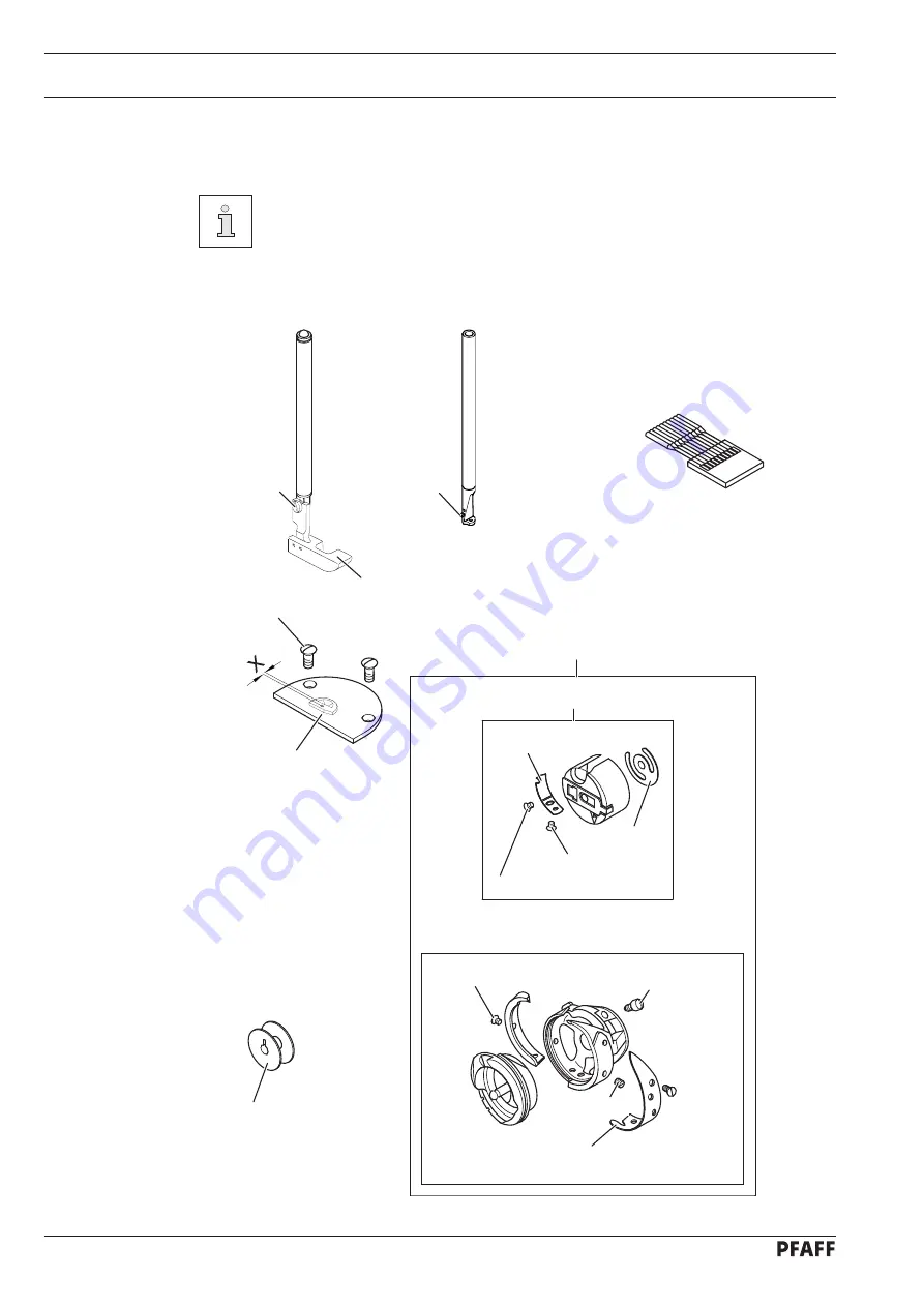
Pfaff 3511-2/01 Скачать руководство пользователя страница 98

Wearing parts

98

13 Wearing 

parts

This is a list of the most important wearing parts.

A detailed parts list for the complete machine is included with the accessories. 

In case of loss, the parts list can be downloaded from the internet address

www.pfaff-industrial.de/pfaff/de/service/downloads

. As an alternative to 

the internet download the parts lists can also be ordered in book form under 

part no. 

296-12-19 009.

134 KK

91-100 296-25(2x)

91-150 890-03/001(

X

= 3,5 mm)

91-150 890-03/002(

X

= 5 mm)

11-108 174-25

11-330 958-15

91-154 921-91

91-262 250-91

91-262 377-91

99-137 192-05

99-137 191-05

99-137 193-05

99-137 194-05

99-137 187-15 (2x)

99-137 190-05 (3x)

99-137 188-15 

99-137 186-05

99-137 189-15 (2x)

91-262 437-05

Содержание 3511-2/01

Страница 1: ...3511 2 01 Instruction manual 296 12 19 010 002 Betriebsanleitung engl 11 06 This instruction manual applies to machines from software version 1 912 19 and serial number 2 736 439 onwards...

Страница 2: ...nstruction manuals whether in whole or in part is not permitted without our prior permission and not without written indication of the source PFAFF Industrie Maschinen AG Postfach 3020 D 67653 Kaisers...

Страница 3: ...5 7 02 Lever for lifting the presser foot 15 7 03 Pedal 16 7 04 Photo sensor 16 7 05 Control panel 17 7 05 01 Screen displays 17 7 05 02 Symbole im Display 17 7 05 03 Function keys 18 8 Installation a...

Страница 4: ...08 Deleting programs in the machine memory 50 10 04 09 Deleting programs on the SD memory card 51 10 04 10 Formatting the SD memory card 52 10 05 Error messages 52 11 Care and maintenance 53 11 01 Ma...

Страница 5: ...jig drive in the sewing direction 81 12 09 02 Position of the jig drive crosswise to the sewing direction 82 12 09 03 Jig drive contact pressure 83 12 09 04 Adjusting the support roller 84 12 10 Adju...

Страница 6: ...sewing tools e g needle roller presser needle plate and bobbin when threading the machine when leaving the machine unattended and during mainte nance work the machine is to be separated from the powe...

Страница 7: ...he duty of the user to only operate the machine in perfect running order It is the obligation of the user to ensure that none of the safety mechanisms are removed or deactivated It is the obligation o...

Страница 8: ...es in the machine which may limit its safety 1 05 02 Specialist personnel Specialist personnel are persons with a specialist education in the fields of electrics electro nics and mechanics They are re...

Страница 9: ...setting or adjusting the machine do not leave any objects on the table nor in the needle plate area Objects may be trapped or flung out of the machine Do not run the machine without take up lever gua...

Страница 10: ...uses of this machine which have not been approved of by the manufacturer are considered to be inappropriate The manufacturer cannot be held liable for any damage caused by the inappropriate use of th...

Страница 11: ...above table approx 300 mm Electrical data Power supply 230 V 10 50 60 Hz Max output 400 VA Fuse protection 1 x 16 A inert Working air pressure 6 bar Air consumption approx 25 l work cycle Noise data N...

Страница 12: ...d various plastic materials The electrical equipment comprises plastic materials and copper The machine is to be disposed of according to the locally valid pollution control regula ti ons if necessary...

Страница 13: ...e machines are only transported in an upright position 5 03 Disposal of packing materials The packing materials of this machine comprise paper cardboard and VCE fibre Proper dis posal of the packing m...

Страница 14: ...struction manual work to be carried out or important information is accentuated by symbols These symbols have the following meanings Note information Cleaning care Lubrication Maintenance repairs adju...

Страница 15: ...ols 15 77 005 1 7 Controls 7 01 On off switch Switch the machine on or off by turning main switch 1 Fig 7 01 7 02 Lever for lifting the presser foot The presser foot is raised by turning lever 1 Fig 7...

Страница 16: ...ewing cycle 0 neutral position 1 no function 2 seam stop Fig 7 03 7 04 Photo sensor The LED 1 in the photo sensor indicates the following status LED shows green light indicates reception LED shows gre...

Страница 17: ...shown with LEDs in the corresponding keys Every time the function keys 2 are operated a key tone sounds as confirmation of the input If the input required is invalid e g because the max permissible va...

Страница 18: ...the key un derneath To convert from double backtack to single backtack reset the number of stit ches for the corresponding seam section End backtacks If this key is pressed the backtack function at th...

Страница 19: ...he parameter input the altered values are stored and the se wing mode is called up Press this key twice to call up the program management function see Chapter 10 04 Program Management Piece Counter Pr...

Страница 20: ...off If the function is switched on in the manual sewing mode the edge trimmer moves to the cutting positi on F3 After the corresponding PC piece counter function has been selected press the key to res...

Страница 21: ...e a stand and table top that can hold the weight of the machine with its motor It is very important to ensure that the stand of the machine is firm and steady also during sewing 8 01 Installation The...

Страница 22: ...lation and commissioning 22 8 01 02 Mounting the spool holder Mount the spool holder as shown in Fig 8 02 Insert the spool holder into the hole in the table top and fasten it with the nuts enclosed Fi...

Страница 23: ...les Connect all plugs as labelled to the control box 1 Screw the earth cable from the sewing head and the main switch to earth point A Connect earth point A to earth point B with earth cable 2 Screw t...

Страница 24: ...w a pressure of approx 6 bar If necessary have this reading correctly set see Chapter 11 04 Checking adjusting the air pressure Have skilled personnel check if the machine can be operated with the ava...

Страница 25: ...g the user level Call up parameter 700 by pressing the keys P or S Use the pedal function to sew one stitch Turn the balance wheel in the sewing direction until the lower edge of the descending needle...

Страница 26: ...be separated from the electricity supply by removing the plug from the mains or switching off the On Off switch 9 01 Inserting the needle Switch off the machine Danger of injury due to uninten tional...

Страница 27: ...winder while at the same time pressing bobbin winder spindle 2 and lever 3 The bobbin fills up during sewing To adjust the bobbin winder tension turn knurled screw 4 The bobbin winder stops automatic...

Страница 28: ...must rotate in the direc tion of the arrow Fig 9 04 1 5 c m 9 03 Removing Inserting the bobbin case Switch off the machine Danger of injury due to uninten tional starting of the machine Removing the...

Страница 29: ...eedle thread Adjusting the needle thread tension Switch off the machine Danger of injury due to unintentional starting of the machine Thread the machine as shown in Fig 9 05 Adjust the needle thread t...

Страница 30: ...nction by pressing the keys Start backtacks and or End backtacks LED is illuminated By pressing the corresponding key A select the desired value for the number of forward stitches A of the start backt...

Страница 31: ...r 1 again Removing the SD memory card Open cover 1 Press the edge of the SD memory card 2 lightly the SD card is ejected Close cover 1 again By moving slide 3 it is possible to activate position LOCK...

Страница 32: ...sewing jig Insert the lining between cloth plate 1 and material clamp 2 so that it is touching guide pins 3 Close the material clamp 2 Place the preliminary cut workpiece for the fullness on material...

Страница 33: ...Preparation 33 9 09 02 Inserting the sewing jig Position the sewing jig 1 in the guide bar on the needle plate and push it until it reaches the stop The machine is ready for operation Fig 9 08 1...

Страница 34: ...in the sewing mode all sewing data relevant for the production is shown on the display Standard operation is in the pro grammed sewing mode It is possible to switch to the manual sewing mode to instal...

Страница 35: ...acks on off Line selection End backtacks on off Parameter input program management Edge trimmer on off Piece counter display on off Jig drive on off Support roller on off Sewing foot raised after thre...

Страница 36: ...tart backtacks on off Alter seam pattern End backtacks on off Line selection Edge trimmer on off Piece counter display on off Jig drive on off Support roller on off Sewing foot raised after thread tri...

Страница 37: ...stitch length 1 2 mm Actual stitch length 8 0 mm Turn 1500 min 1 Seam section 5 Stitches 35 Stitch length 2 2 mm Speed 2200 min 1 Turn 23 mm Switch on the machine Activate mechanic level b see Chapte...

Страница 38: ...elect the second seam section Activate the top line of the display LED in the key is illuminated Press the key D to select the desired stitch length value e g 2 2 mm Sew the second seam section using...

Страница 39: ...ot illuminated Press the key S to select the fifth seam section SL 2 2mm 2200 10 3 66 Activate the top line of the display LED in the key is illuminated Press the key D to select the desired stitch le...

Страница 40: ...turn e g 23 mm Switch on the turn corner function for the seam section The turn is carried out Activate the bottom line of the display LED in the key is not illuminated Conclude the teach in mode LED...

Страница 41: ...ered e g 10 by pressing the key P If necessary alter the stitch length see Chapter 9 06 Entering the stitch length If necessary alter the start and end backtacks see Chapter 9 07 Entering the start an...

Страница 42: ...UT edge trimmer SL stitch length BTM OFF thread monitor or Software version SL 2 2mm 3 3 3 3 10 0 5 Press the key D to alter the number of stitches for the waistband extension After the appropriate fu...

Страница 43: ...ropriate machine see Chapter 10 04 08 Formatting the SD memory card 10 04 01 Calling up the program management Switch on the machine If necessary call up the manual sewing mode LED in the key is not i...

Страница 44: ...eys L it is possible to scroll within the display of the machi ne memory programs 1 99 Only assigned program spaces existing seam patterns are displayed Press keys A to call up the other menu items of...

Страница 45: ...eys L it is possible to scroll within the display of the SD me mory card programs 1 99 Only assigned program spaces existing seam patterns are displayed Press keys A to call up the other menu items of...

Страница 46: ...the menu item by pressing on the keys L Press the keys D to select the programs which are to be copied from the machine memory to the SD memory card programs 1 99 Press the keys P to select the progra...

Страница 47: ...04 01 Calling up the program management Press the keys A until the appropriate menu item appears Confirm the selection of the menu item by pressing on the keys L Confirm the copying process by pressin...

Страница 48: ...s Confirm the selection of the menu item by pressing on the keys L Press the keys P to select the programs which are to be copied from the SD memory card to the machine memory programs 1 99 Press the...

Страница 49: ...04 01 Calling up the program management Press the keys A until the appropriate menu item appears Confirm the selection of the menu item by pressing on the keys L Confirm the copying process by pressin...

Страница 50: ...he keys A until the appropriate menu item appears Confirm the selection of the menu item by pressing on the keys L Press the keys D to select the programs which are to be deleted from the machine memo...

Страница 51: ...he keys A until the appropriate menu item appears Confirm the selection of the menu item by pressing on the keys L Press the keys P to select the programs which are to be deleted from the SD memory ca...

Страница 52: ...s keys A to call up the other menu items of the program management FORMAT 10 05 Error messages If a malfunction occurs an error code appears on the display together with short instruc tions In additio...

Страница 53: ...ing factors Single or several shift operation Amount of dust resulting from the workpiece It is therefore only possible to stipulate the best possible cleaning instructions for each indi vidual case F...

Страница 54: ...n the sewing head support Fill oil through hole 1 into the reservoir 2 up to the level of the front edge see ar row Return the machine to its up right position using both hands Danger of injury by cru...

Страница 55: ...the air hose at the air filter regulating unit Emptying the water bowl Water bowl 1 empties itself automatically when the air hose is disconnected from the air filter regulator Cleaning the filter Un...

Страница 56: ...ceding and following chapters must be observed Screws nuts indicated in brackets are fastenings for machine parts which must be loosened before adjustment and tightened again afterwards If not otherwi...

Страница 57: ...ired position Insert blocking pin 1 in hole Turn balance wheel slightly back and forth until blocking pin engages crank 2 Needle bar position 0 6 mm past t d c Set needle bar roughly at required posit...

Страница 58: ...has been removed Turn toothed belt sprocket 1 according to Requirement and push on toothed belt 2 When installing the motor pay attention to the correct position of shaft flange shock absorber and mo...

Страница 59: ...justing the needle height Requirement When the needle bar is positioned at t d c the needle point should be 9 mm above the needle plate Move needle bar 1 screw 2 without turning it according to the re...

Страница 60: ...y above the needle hole Loosen screws 1 2 and 3 Move the needle bar frame 4 according to the requirement Tighten screw 2 and turn screw 3 slightly Via screw 1 bring the retracted guide bolt to the eye...

Страница 61: ...hed belt should be tightened in such a way that when the gauge is pushed onto the toothed belt the marking in the gauge window corresponds to the marking on the bushing 1 2 Align hook shaft bearing 1...

Страница 62: ...after approx 10 seconds a mark should be made by a fine stripe of oil on the strip of paper placed over the needle plate cutout 1 2 The adjustment is only necessary if the wick has been replaced When...

Страница 63: ...be 0 8 mm below the hook point Between the projection of the bobbin case position finger 4 and the bottom of the re taining groove there should be a distance of 0 5 mm 1 2 3 Using the adjustment pin p...

Страница 64: ...mm When the thread loop is at its largest when going around the hook the thread check spring must have moved by approx 1 mm 1 2 Turn thread tension 1 screw 2 according to requirement 1 Turn thread te...

Страница 65: ...iably With the bobbin winder off the friction wheel 5 must not be driven by the drive wheel 1 The bobbin winder must turn off automatically when the thread level is approx 1 mm from the edge of the bo...

Страница 66: ...66 12 05 09 Presser foot pressure Requirement The sewing jig should be transported reliably The presser foot pressure should be as low as possible 1 2 Turn screw 1 in accordance with the requirement F...

Страница 67: ...When the edge trimmer is switched off Lever 5 should be slightly supported without play and The knife should not move when the balance wheel is turned 1 2 Adjust screw 1 nut 2 in accordance with requ...

Страница 68: ...utting motion Requirement When the edge trimmer is switched on the knife should be at the bottom of its stroke when the needle bar is at b d c Adjust eccentric 1 two screws 2 in accordance with the re...

Страница 69: ...Requirement When the knife is at the bottom of its stroke the front edge of the knife blade should be approx 0 5 mm below the top edge of the stationary knife Adjust knife 1 screws 2 according to the...

Страница 70: ...in sewing direction Requirement When the needle bar is at b d c the knife blade should be at a distance of 1 mm from the edge of the stationary knife Adjust knife bracket 1 screw 2 according to the r...

Страница 71: ...ouching the stationary knife 6 without counter pressure and Be at a 0 1 mm slant to the stationary knife 6 1 2 Loosen screws 1 Adjust eccentric 2 screw 3 in accordance with the requirements Tighten sc...

Страница 72: ...12 06 06 Knife position crosswise to sewing direction Requirement The knife should be resting on the stationary knife with light pressure Adjust knife bracket 1 screw 2 according to the requirement Fi...

Страница 73: ...ed roller lever 4 should be at the lowest point of the control cam When the needle bar is positioned at 1 8 mm after b d c needle rise position roller lever 4 should engage in the appropriate recess o...

Страница 74: ...r 5 must be horizontal It must not graze anything when it is opera ting 1 2 Remove knife 1 screw 2 Move needle bar to its BDC Loosen stop 3 screws 4 Position thread catcher 5 screw 6 manually in front...

Страница 75: ...t edge of the thread cat cher see arrow 1 2 Bring the needle bar to BDC Slide knife 1 under the locking tab and align according to requirement 1 Tighten screw 2 lightly Adjust thread catcher carrier 3...

Страница 76: ...e front point of reversal of thread catcher 4 the tip of the thread catcher cutout should be 1 mm in front of the bobbin case position finger 5 Position roller lever 1 at the lowest point of the contr...

Страница 77: ...oint of reversal Double the thread and insert into catcher cutout Carry out trimming operation manually If the threads are not cut according to the requirement align thread catcher 1 screws 2 with kni...

Страница 78: ...net lift should be 1 5 mm When the magnet 5 is operated by hand there should be a distance of at least 0 5 mm between the tension discs 6 1 2 Adjust disc 1 nuts 2 according to the requirement Adjust s...

Страница 79: ...12 07 07 Readjusting the control cam Requirement When the take up lever is in its t d c control cam 1 should have moved thread catcher 3 Adjust control cam 1 screws 2 according to the requirement Fig...

Страница 80: ...r foot lift Requirement When the automatic presser foot lift is activated there should be a clearance of 7 mm bet ween the presser foot and the top part of the needle plate Move magnet 1 screw 2 accor...

Страница 81: ...12 09 01 Position of the jig drive in the sewing direction Requirement Drive 1 should be parallel to and at a distance of 6 mm to the edge of the bed plate Adjust drive 1 screws 2 in accordance with...

Страница 82: ...09 02 Position of the jig drive crosswise to the sewing direction Requirement Drive wheel 3 should firmly touch the sewing jig at all times Adjust piston rod 1 nut 2 in accordance with the requirement...

Страница 83: ...03 Jig drive contact pressure Requirement The sewing jig must be transported reliably at all times The contact pressure should be as low as possible 1 2 Adjust throttle 1 in accordance with the requi...

Страница 84: ...justing the support roller Requirement When the support roller 3 is extended the sewing jig should be guided parallel to the edge of the cover plate Adjust unit 1 screws 2 in accordance with the requi...

Страница 85: ...Requirement The distance between the retainer 1 and the edge trimmer 3 should be as short as possible Retainer 1 and edge trimmer 3 should not touch each other 1 2 Adjust retainer 1 screw 2 in accorda...

Страница 86: ...2 3 Adjust photo sensor 1 screw 2 in accordance with requirement 1 If necessary correct the position of the adhesive tape 3 in accordance with requirement 2 Adjust stop 4 nut 5 in accordance with requ...

Страница 87: ...he current user level is shown on the display 12 12 01 Selecting the user level As a standard when the machine is switched on it is in user level a Below is a description of how to call up the service...

Страница 88: ...12 12 03 List of parameters Press the keys P to select the desired parameter e g parameter 660 bobbin thread monitoring Press the keys L to set the desired value for the parameter e g value 2 bobbin...

Страница 89: ...C 0 1 1 452 Input operation lock 1 on 0 off no function B C 0 1 1 5 521 Needle position if sewing stop before seam end 1 needle position 2 take up lever raised 0 needle position 1 lowered B C 0 1 1 5...

Страница 90: ...art thread catcher B C 0 255 164 715 Switch on time for thread wiper ms B C 0 2000 90 718 Stop brake tacting 0 brake off B C 0 100 0 719 Tacting adjustment A4 presser foot 0 100 power up B C 10 60 40...

Страница 91: ...10 884 Proportional sensitivity of the speed control unit general B C 1 24 10 885 Integral sensitivity of the speed control unit C 10 80 50 886 Proportional sensitivity of the positioner C 1 15 8 887...

Страница 92: ...ighth step C 1 4 2 1103 Maximum current stepper 1 C 1 100 90 1104 Reducing current stepper 1 C 0 60 50 1105 Start stop time for stepper 1 time for one step at start stop speed C 10 4000 250 1106 Pulse...

Страница 93: ...t low at initialisation Error 66 Short circuit 2 Error 68 Extint low in operation Error 69 No increments stepper start signal Error 70 Motor stalling Error 71 No incremental plug Error 74 No external...

Страница 94: ...ware test Switch on the machine Activate service level C see Chapter 12 12 01 Selecting the user level Select parameter 797 and set it at ON by pressing the appropriate key Test block 1 appears on the...

Страница 95: ...IWG All 16 switch positions can be called up by operating the pedal If all positions from 2 1 0 1 1D to 12D appear on the display the set value sender is in order The actual value can be checked by tu...

Страница 96: ...delete seam parameters or seam patterns or to carry out a cold start Press and hold key P and key L and switch on the machine RESET Y N Parameter reset Press the P key to carry out a parameter reset...

Страница 97: ...PC serial interface or appropriate USB adapter and the machine control unit RS232 Switch on the PC and start the PFP boot program Select the machine type Press the programming button An extra program...

Страница 98: ...ustrial de pfaff de service downloads As an alternative to the internet download the parts lists can also be ordered in book form under part no 296 12 19 009 134 KK 91 100 296 25 2x 91 150 890 03 001...

Страница 99: ...Wearing parts 99 91 171 049 05 99 137 151 45 91 700 996 15 95 774 464 25 91 171 042 05 11 108 087 15 11 108 084 15 2x 91 262 235 15 91 262 184 15 91 108 222 15 91 264 338 15 91 165 629 05...

Страница 100: ...dge trimmer on off Cutting waste suction extraction Pressure roller forwards reverse Support roller forwards reverse The actuators and valves are in the machine s ready position main switch ON compres...

Страница 101: ...ntrol panel S31 A2 X4A Jig feed stepper SM1 X5 Inputs and outputs X6 Photo sensor B6 X7 Bobbin thread monitor option X21 Jig feed stepper SM1 X22 Y2 Edge trimmer 731 X23 Y3 Blowing X24 Y4 automatic pr...

Страница 102: ...102 Circuit diagrams Version 22 05 06 91 191 500 95 Part1...

Страница 103: ...103 91 191 500 95 Part 2 Version 22 05 06 Circuit diagrams...

Страница 104: ...104 Circuit diagrams Version 22 05 06 91 191 500 95 Part 3...

Страница 105: ...105 91 191 500 95 Part 4 Version 22 05 06 Circuit diagrams...

Страница 106: ...PFAFF Industrie Maschinen AG Postfach 3020 D 67653 Kaiserslautern K nigstr 154 D 67655 Kaiserslautern Telefon 0631 200 0 Telefax 0631 17202 E Mail info pfaff industrial com...

Отзывы: