Petwa 75V Скачать руководство пользователя страница 3

2

3

 

Read this manual thoroughly to become familiar with the  


device and its capabilities before installing or operating your  


Water Filter. Failure to follow instructions in this manual  


could result in personal injury or property damage. This    


manual will also help you to get the most out of your filter.

 

This system is intended for use on municipal water only and  


its installation must comply with all State, provincial or local  

 regulations. Check with your local public works department  


for plumbing and sanitation codes. In the event the codes  


conflict with any content in this manual the local codes    


should be followed. Consult your licensed plumber for  


installation of this system.

 

This water filter is designed to operate on pressures of 30 psi  


to 125 psi. If the water pressure is higher than the maximum  


use a pressure reducing valve in the water supply line to the  

 filter.

 

This unit is capable of operating at temperatures between   


40°F and 110°F (4°C - 43°C). Do not use this water filter on hot  


water supplies.

 

Do not install this unit where it may be exposed to wet  


weather, direct sunlight, or temperatures outside of the    


range specified above.

 

Avoid pinched o-rings during installation by applying  


(provided with install kit) NSF certified lubricant to all seals.

 

Filters are commonly exposed to high levels of  iron,  


manganese, sulfur, and sediments. Damage to pistons, seals,  


and or spacers within the control valve are not covered in    


this warranty due to the harsh environment.

 

It is recommended to regularly inspect and service  the    


control valve on an annual basis. Cleaning and or replacement  


of piston,  seals,  and or spacers may be necessary  depending  


on how harsh the conditions are.

 

Do not use water that is microbiologically unsafe without    


adequate disinfection before or after this system.

 

This publication is based on information available when    


approved for printing. Continuing design refinement could  


cause changes that may not be included in this publication.  


The manufacturer reserves the right to change the  


specifications referred to in this literature at any time,  


without prior notice.

READ THIS PAGE FIRST 

BEFORE STARTING INSTALLATION

INSTALL NOTES &

SAFETY MESSAGES

Watch for the following  

messages in this manual:
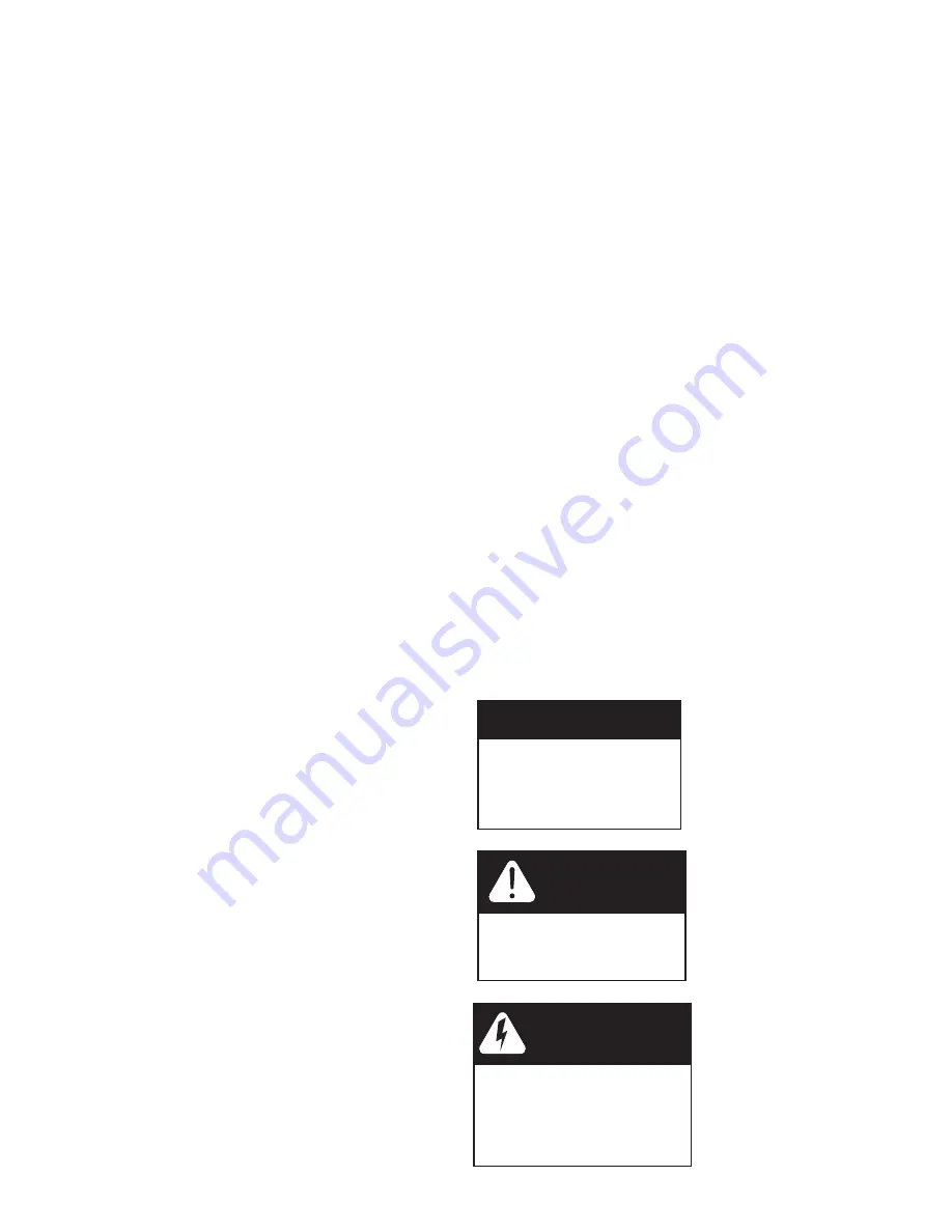
NOTE

Do not remove or destroy 

the serial number. It must be 

referenced on request  

for warranty repair or  

replacement

CAUTION!

Disassembly while  

under pressure can 

result in flooding.

WARNING!

ELECTRICAL SHOCK  

HAZARD!

 UNPLUG THE UNIT 

BEFORE REMOVING THE  

COVER OR ACCESSING ANY 

INTERNAL CONTROL PARTS

NOTE:


used to emphasize 

installation, operation or 

maintenance information 

which is important but does 

not present a hazard.

CAUTION:


used when 

failure to follow directions 

could result in damage to 

equipment or property. 

WARNING:


used to 

indicate a hazard which 

could cause injury or death if 

ignored. 

Содержание 75V

Страница 1: ...l contains important maintenance procedures for the continued proper operation of your unit These MUST be performed regularly for your warranty to remain valid 2 Read all instructions carefully before...

Страница 2: ...NSTRUCTIONS 20 MAINTENANCE INSTRUCTIONS AND SCHEDULE 22 IMPORTANT WARRANTY AND MAINTENANCE INFORMATION 23 CARE OF YOUR SOFTENER 24 SERVICING COMPONENTS 24 RES UP FEEDER INSTALLATION INSTRUCTIONS 24 SE...

Страница 3: ...ls of iron manganese sulfur and sediments Damage to pistons seals and or spacers within the control valve are not covered in this warranty due to the harsh environment It is recommended to regularly i...

Страница 4: ...ditioner regenerates it will display 2 numbers for capacity 1 will be total capacity the other will be 70 of capacity The unit counts down to the end of the 70 then calculates how much of the 30 you u...

Страница 5: ...operated at temperatures between 40 F and 110 F 4 C 43 C Working Pressure This water softener must be operated on pressures between 30 psi to 125 psi If the water pressure is higher than 125 PSI use...

Страница 6: ...6 Cabinet Model B Twin Tank Model A A B PW75V 75 44 8 PW75V 100 48 9 PW75V 150 54 10 PW75V 200 52 12 PW75V 250 54 13 PW75V 300 65 14 PW75V 75C 35 9 PW75V 100C 35 10 SYSTEM DIMENSIONS...

Страница 7: ...x 34 7 18 9 x 18 9 x 65 6 270 0 122 2 52 8 23 9 BTR 145 Black 42 3 159 7 20 3 x 37 4 21 9 x 21 9 x 72 2 385 0 174 2 65 6 29 8 BTR 200 Grey 53 0 200 3 23 0 x 40 5 24 6 x 24 6 x 84 700 0 316 7 125 0 56...

Страница 8: ...175 225 275 salt grid system 918 36 2 salt tank body salt tank lid 7 3 20 35 1028 186 40 5 517 175 225 275 brine well and brine valve salt grid system 585 23 BTR 200l label BTR70 BTR145 BTR100 BTR200...

Страница 9: ...avoid loss of the small parts keep them in the parts bag until you are ready to use them What is included in the box For Models 75 100 150 200 you will expect the following 1 Control Valve 2 Tank 3 P...

Страница 10: ...3 for 250 and 300 4 Drain Line and Hose Clamp Not Included with some models 5 Brine Tank Assembly Models 250 300 will get Adaptor and Oring Shown 1 Tank 2 Control Valve Distributor Tube Inside the Ta...

Страница 11: ...ECTION OF CABINET MODEL 1 Cabinet with Valve attached 2 Parts Box 3 Drain Line and Hose Clamp Not Included with some models 2 Parts Box 2X 1 Straight Adapter Bypass Tool 2 X 3 4 Elbow Adapter Transfor...

Страница 12: ...ch provides information of Serial and Date of Manufacture of complete system Both Serial labels are important for troubleshooting Please record these numbers for future use on page 23 in the maintenan...

Страница 13: ...them Tools Required for Installation NOTE We recommend installation only be completed by a competent installer or plumbing professional to insure this product is installed in accordance with local plu...

Страница 14: ...the valve into the threads in the fiberglass tank tightening securely into tank Note Ensure that the internal O ring in the valve fits securely over the riser tube Silicone grease part 92360 or other...

Страница 15: ...et of the water softener and to the outside faucets 3 Make sure the bypass is attached well to the control valve Connect the straight or elbow connectors to the bypass with red clips Connect the inlet...

Страница 16: ...tighten the nut In many cases the brine line already come installed from the factory Leave the other end of the brine line tube inside the brine tank f For installation of brine tank at the installati...

Страница 17: ...Installation Connect Softener to the HousePlumbing Any solder joints near the valve must be done before connecting any piping to the valve Always leave at least 6 152 mm between the valve and joints...

Страница 18: ...ater Cold Filtered water Cold Raw water Water Heater Hot Soft Water Upflow Water Softener Filter In In Out Out Cold Soft Water To Outside Faucet In Out CABINET WATER SOFTENER INSTALLATION CAUTION Neve...

Страница 19: ...Water to BrineTank Open the brine tank cabinet salt lid and add water as per the chart below Do not add salt to the brine tank at this time BT 100 2 5 US Gallons BT 145 3 25 US Gallons BT 200 5 5 US G...

Страница 20: ...tank The unit will automatically fill the water to the correct level when it regenerates Start up and programming complete Unit is now operational 4a Open the inlet on the bypass valve slowly and all...

Страница 21: ...owing the unit to use up any remaining salt and then thoroughly cleaning out the brine tank Allow four hours to produce a brine solution then manually regenerate the softener Cleaning of your Brine Sa...

Страница 22: ...salt in tank will both effect the units capacity and result in hardness slippage Should either of these situa tions happen or the unit fails to regenerate for any other reason please first correct the...

Страница 23: ...ar depending on the inlet water quality and water usage The seals and spacer cartridge should be inspected cleaned or replaced every year depending on the inlet water quality and water usage Please re...

Страница 24: ...bottle Insert the other end of the tube completely into the hole in the brine well cap Automatic feeding will start in a few hours Res Up Feeder Installation Instructions Round BrineTank continued 1 I...

Страница 25: ...icing 1 Turn off water supply to conditioner a If the conditioner installation has a 3 valve bypass system first open the valve in the bypass line then close the valves at the conditioner inlet outlet...

Страница 26: ...owed by timer assembly 6 Replace the piston assembly and reverse following steps in this section Remove 3 X Screws Plate Seal and Spacer Brine Valve Assembly Piston Assembly Remove front cover Remove...

Страница 27: ...the impeller out from the coupling and clean it 4 Replace meter and re assemble the removed components back in the section 1 Remove two screws of the injector cap 2 Pull the Injector Cap Out Remove t...

Страница 28: ...ted on the control valve Please see steps below To enter the programming press and hold the MENU button for 5 seconds to unlock the screen Press and hold the Up and Down Arrows Press the down arrow to...

Страница 29: ...2 Clean replace drain line washer 1 Remove front cover 2 Remove Pin 3 Remove Gear 4 Remove 6 screws 5 Remove plate 6 Replace motor Remove front cover Replace with new PCB and reconnect cables Disconn...

Страница 30: ...00 14 x 65 25030001 and 50040039 Not Available Not Available 50010010 95604 75C 9 x 35 25010028 Not Available Not Available 50010010 95600 100C 10 x 35 25010043 95601 Downflow Softener AFTER SERVICING...

Страница 31: ...nt75 Display Board 1 B23 60095618 PC Board 1 B22 60095619 75Valve Cover Black 1 B21 60095620 Face Label 1 B20 60010579 Screw M3 30 2 B19 60095621 Micro Switch 2 B18 60095622 Screw ST3 5 16 BT 7 B17 60...

Страница 32: ...2 A23 92381 BrineValve Injector Stem Assembly 1 A22 60010081 BLFC Button Retainer 1 A21 60010110 BLFC 0 3GPM 1 A20 60010083 O ring 14 1 8 1 A19 13244 Copper Fitting 1 A18 60010087 BLFC Ferrule 1 A17...

Страница 33: ...05056214 Bypass Shaft Outlet 1 20 60095614 05030013 O ring 30 2 65 2 19 60010740 05056149B Shaft Seal 2 18 60010069 05056172N Plug Clip Red 2 17 60010740 21709004 Shaft Clip Red 2 16 60010209 0505614...

Страница 34: ...e Assy 1 15 Softener Cabinet Grey 1 14 Softener Low Cover Black 1 13 Softener High Cover Black 1 12 Transparent Plate Holder Left 1 11 Transparent Plate 1 No Part Description Qty 10 Transparent Plate...

Страница 35: ...Cancel Press To Confirm Setting Complete Press To Return Standby interface Auto On Auto On Auto On Dealer information input letter by letter PRESS MENU KEY AND SCROLLTO MAIN MENU THEN PRESS SET TILL I...

Страница 36: ...t Mode Economy Mode Press To Cancel Press To Confirm Setting Complete Press To Return MAIN MENU REGENTIME This setting determines the time of day to perform a scheduled regeneration SYSTEM CAPACITY In...

Страница 37: ...Initial Setup Interface Language Region Valve Meter Radio SaltVs Effiiency Setting Calculation SaltVs Effiiency E 3 0 lbsVs 5000 Grs S 06 0 lbsVs 4150 Grs H 12 0 lbsVs 2500 Grs Setting Complete Press...

Страница 38: ...Cu ft 1 50 Cu ft 2 00 Cu ft 2 50 Cu ft 3 00 Cu ft 9 REFILL RATE 0 7 GPM 10 REGEN MODE Meter Delay 11 BW RINSE OVERRIDE BACKWASH OFF OFF RINSE OFF 12 EMERGENCY REGEN OFF 13 Regen Cycles BACKWASH 4 BRI...

Страница 39: ...1 00Cu ft 1 50Cu ft 2 00Cu ft 2 50Cu ft 3 00 Cu ft 9 REFILL RATE 0 7 GPM 10 REGEN MODE Meter Delay 11 BW RINSE OVERRIDE BACKWASH OFF OFF RINSE OFF 12 EMERGENCY REGEN OFF 13 Regen Cycles BACKWASH 4 BRI...

Страница 40: ...Toll Free 1 877 288 9888 Regina SK Cambridge ON Carmel IN Pottstown PA Phoenix AZ 54672 09 18...

Отзывы: