Installation
2
0
1
8
-1
2
39
Removing Ex-q modules
The pull and plug concept with a built-in removal lever on every module enables quick
installation and permits safe module replacement during operation. In this way, the exchange
can take place using the built-in removal lever and the two-step removal procedure.
1. Disconnect the cordset from the front socket on the module.
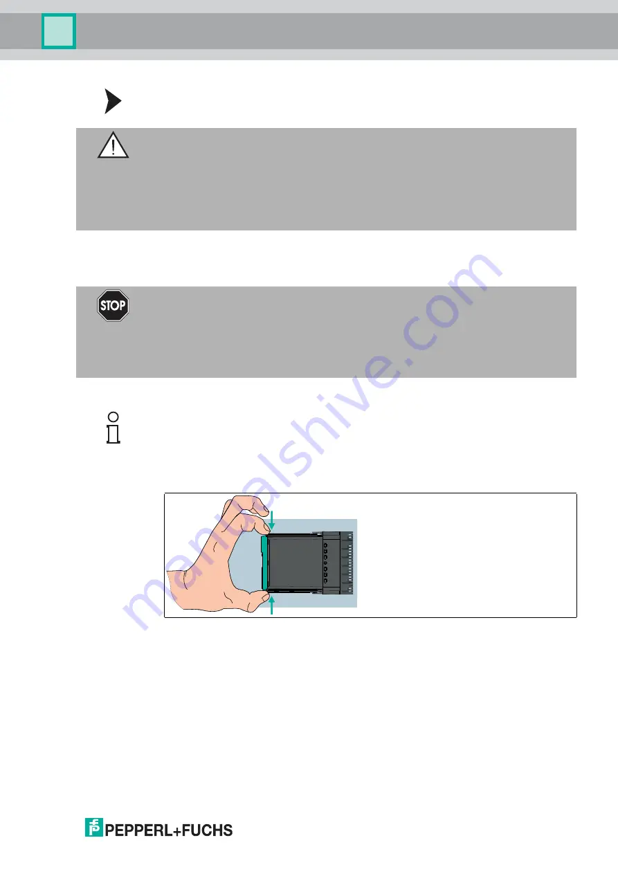
2. Remove the first rear catch on the backplane. To do this, press the integrated removal levers
on the top and bottom of the module using your thumb and index finger.
Figure 3.12
Integrated removal device
3. Pressing down with your thumb and index finger, push the removal lever as far as it will go
toward the backplane. Use your thumb and index finger to grip the released module
enclosure and pull the module out by a few millimeters until you feel resistance from the
second rear catch.
Warning!
Explosion hazard due to damaged modules
Forcibly removing modules or using unsuitable tools can damage the module or the backplane,
meaning that explosion protection can no longer be guaranteed.
Only remove modules using the built-in removal device. The built-in removal device forces a
two-stage removal process that contains any potential ignition spark within the pressure-
resistant terminal area.
Danger!
Explosion hazard when removing field connections on the module.
I/O modules with Ex-e front ports require additional measures to be disconnected during
operation.
Do not connect or disconnect the I/O module with Ex-e front connections while the circuit is live
and while it cannot be guaranteed that the surroundings do not present an explosion hazard.
Note!
I/O modules with intrinsically safe front connectors or modules without front connectors (e.g.,
power supply, bus termination module) can be removed while operation is ongoing.


