background image

76180 EM -54/73- 


Set the camera as follows. 

Capture mode: AV (Aperture-priority) mode and Set AV 22 (FNo.22), ISO speed: 200, Focus 
mode SW: MF, Exposure compen1/2EV,  Recorded pixels: L (Default setting), 
Quality Level: Best. 


Turn the distance ring of the lens to infinity (

). 


Take the pictures of the light box from on 3cm. 


Display the images on the computer with image viewing software. 


Set the image to life size (1:1) and confirm dust. (Better to make clear the position of dust 
with such as coordinate)       
If you see dust clearly on image, there is possibility that the dust enters into the inside of 
CCD. (Disassembly and cleaning or replace T600)           

 
[Cleaning method of dust] 
[CAUTION] 1, For safety, use two type of power source for cleaning (AC adapter and full 

capacity of battery) 

2, Do not use a brush-less blower and a spray type blower to clean the CCD 

because there is a possibility that dust enters into the inside of CCD.   


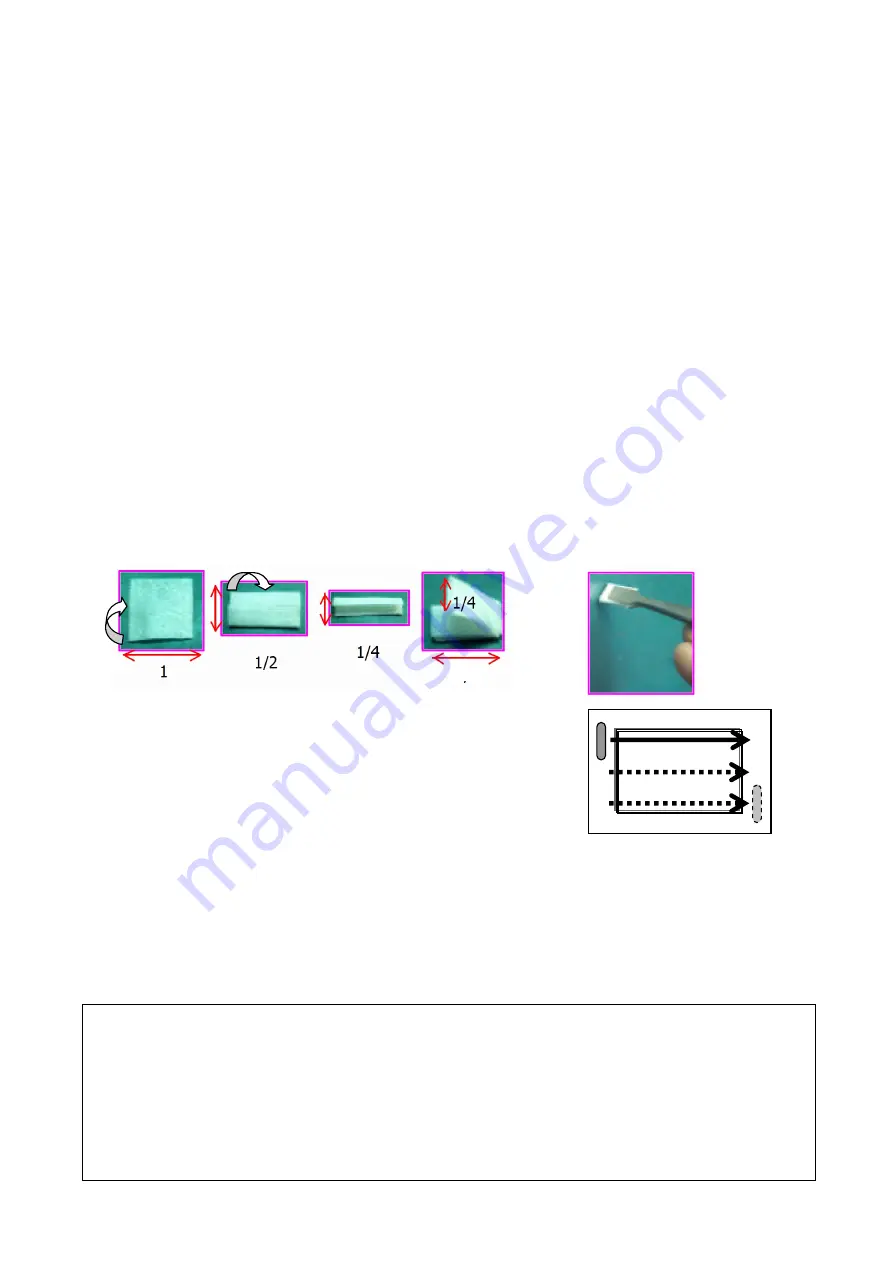
Cut the Clean wipe-P about 1/4 (50x105mm) and hold the Clean wipe-P 7-8mm width. 


Turn the main SW to ON and remove the lens. 


Set [Sensor Cleaning] on the Main menu to ON. 


Select [Mirror up] on the [Sensor Cleaning] screen by the four-way controller. 


Press the OK button. The mirror is locked in the up position. 


Dip Clean wipe-P: 95901 A15 in the Solvent.   


Wipe the surface of CCD from upper left to right and repeat 3-4 times until lower right

You can confirm dust or trace of wipe by cleaning at under the bright light source.   


Turn off the power and return to step (1) of the confirmation then confirm dust. 

[Supplement] Dust on the CCD 
Cause of dust into the camera. 

 Dust enters from outside of the camera when changing the 

lens. Dust stick by moving mirror or shutter.   

According to CCD characteristic the static electricity occurs when taking a picture and so the 

condition is dust stick easily. Besides customer can find dust 
easily by viewing image by the computer. 

It is very difficult to remove dust completely therefore, before cleaning the camera, explain to 
customer for cleaning as much as possible.       

1/8

Содержание ist D

Страница 1: ...PRODUCT No 76180 PENTAX Corporation Service Planning Section 03 04 H Y ENGLISH TM ...

Страница 2: ...Assembly procedure of main body 26 FW FIRMWAR 56 1 Checking Firmware Version 56 2 Updating Firmware Version 1 56 3 Updating Firmware Version 2 57 TECHNICAL INFORMATION 58 Battery consumption current 58 Block diagram 59 Circuit diagram 60 Table of Error Code Digital adjustment 61 AE Program line and APEX chart 62 76180 PROGRAM SOFTWARE FLOW CHART 63 INFORMATION FOR PREPATION 70 Table of Jigs Tools ...

Страница 3: ...ck ON use for service 5 FW version check OFF use for service 2 Installing procedure of the Adjustment Software Setting of the Computer Turn on the test computer Place the Programmed software of 76180 95901 P401 00B into the CD ROM drive Copy the 76180 folder from the Programmed software contained in the CD ROM to C drive as shown in the picture below Copy the file from each folder 01 04 of ModeSET...

Страница 4: ...II Assembly procedures of Front Housing Block 15 1 Front Housing Block 15 2 0 B52 B62 15 3 0 M22 15 4 0 G100 16 5 CONF Checking the Mirror Function 17 6 A104 18 7 ADJ Positioning 1st and 2nd Mirror 18 8 0 J201 A163 19 9 0 L3 L2 19 10 M301 20 11 ADJ Viewfinder Focus Parallax 20 11 1 Parallax 20 11 2 Viewfinder Focus 20 12 0 J100 21 13 M51 21 14 ADJ Positioning 0 O170 SI LED 21 15 0 O100 22 16 0 M10...

Страница 5: ...T100 and 0 T600 36 16 2 Writing FW 37 17 A102 Front Cover 37 18 A153 Front Cover Left 38 19 A201 Back Cover 38 20 ADJ Positioning 0 J100 39 21 0 A301 Top cover 39 22 CONF Function check Ⅲ 40 22 1 Preparation 40 22 2 CONF Static Current 41 22 3 CONF Preview LCD panel illumination 41 22 4 CONF Switch Function 41 22 5 CONF AF SI Superimpose Function 42 22 6 CONF Shooting Playback Function 42 22 7 CON...

Страница 6: ...ing function 49 28 2 Confirmation of the Exposure value for reference 49 28 3 Confirmation of White Balance 49 28 4 Confirmation of the Battery Exhaustion Warning 51 28 5 Confirmation of AF Focus Position by FI Focus Indicator 51 28 7 Cleaning the CCD 53 28 8 Default setting 55 ...

Страница 7: ...move the bottom cover yet Open the battery cover and then lift up A401 from rear side as shown in the figure below 0 A412 A419 Battery cover shaft Unsolder a blue wire and then remove A401 from the main body A421 Peel off PT x6 A434 CNL B1 4x1 6 A424 Reset switch Unsolder two lands 2 0 A301 Top Cover TY CNS1 4x2 5 Pop up the built in flash A70 Screw Ni Inside the battery chamber A61 Screw 2 5mm A6...

Страница 8: ...re below CAUTION Be careful short and electric shock when handling the camera Unsolder 4 lead wires Blue Black Brown Green Q100 Peel off T72 20x15 Unsolder 6 lands T51 Unsolder a black lead wire A330 Remove the top cover 0 A301 from the main body M311 DT 3 A201 Back Cover Insert the CF card to the camera to remove T691 T691 Pull out T691with care to prevent damage Remove the CF card with pressing ...

Страница 9: ... terminal Disconnect the connector terminal of T905 from 0 O301by using the tweezers with care to prevent damage A201 4 A153 Front Cover Left CNL D1 7x2 5 2pcs A153 5 A102 Front Cover CNL D1 7x3 0 A102 6 0 T700 CF P C Board assy 0 T950 Disconnect both connector terminals of 0 T950 from 0 T600 and 0 T700 Disconnect the flexible board of T100 from the connector terminal of T600 ...

Страница 10: ... 5 3pcs There are two washers at the USB part underneath 0 T750 Turn up 0 T600 0 T750 and T960 from left side as shown in the figure below 0 T600 Disconnect the connector terminal of 0 T960 from 0 T600 CCD side 0 T750 Disconnect the flexible board of 0 T960 from the connector terminal of 0 T750 8 Around Pentaprism 1 Unsolder 7 lands 0 O170 Peel off T74 x2 20x10 Peel off T100 from DT Peel off T64 2...

Страница 11: ... for CE mark A5 T62 10 A49 Remote control base plate Peel off A427 8x10 and A425 10x20 for CE mark Unsolder 5 lead wires Peel off the flexible board of remote control Peel off the flexible board of T100 CNL D1 4x5 0 A49 Unsolder 2 lead wires Yellow Black Disconnect the flexible board of T301from 0 T100 CNL D1 4x4 0 Cable release socket ...

Страница 12: ...rd of T100 from the connector terminal of 0 T800 Peel off the flexible board of the cable release socket from DT CNL D1 7x2 5 2pcs 0 Q200 CNL D1 7x2 5 2pcs Unsolder 4 lands 0 T800 0 T800 is removed with T905 Power supply cable 12 T301 Mount P C Board Peel off T69 8x15 x2 from T301 Unsolder 5 lead wires Disconnect the flexible board of T301 from the connector terminal of 0 T100 Unsolder 2 lead wire...

Страница 13: ... Unsolder 2 lead wires Red Black S250 Unsolder 2 lead wires Yellow White T970 Unsolder 3 lead wires Orange Brown Black E000 14 0 A3 Bottom Plate assy CNL D1 7x2 0 2pcs A422 A423 Unsolder 2 lands T301 T907 Unsolder a gray lead wire T81 for CE mark Peel off T301 and T81 from bottom plate T81 will remove with a lead wire TY CSM1 7x4 0 2pcs TY CNL D1 7x4 0 2pcs A429 lug plate for CE mark CSM1 7x2 5 CN...

Страница 14: ...e of 0 T100 If there is a lug plate remove it by loosening screw T903 2pcs BO1 5 2pcs A17 2pcs CSM1 7x2 5 TY CSM1 7x4 0 A429 lug plate for CE mark TY CNL D1 7x4 0 2pcs A6 If there is a lug plate remove it by loosening screw 16 Front Housing Block TY CNL D2 0x9 0 TY CNM2 0x6 0 2pcs CNL D1 7x2 5 Main base plate 17 0 E000 Shutter Block TY CNL D1 7x4 0 2pcs CNL D1 7x2 5 2pcs A13 A429 A429 A429 ...

Страница 15: ...15 A13 A14 A71 x2 Shoulder screw TY CNL D1 7x2 5 0 E000 A65 x4 Screw A2 18 Battery Chamber and Related Parts Unsolder 7 lead wires Unsolder 2 lands T907 DT Unsolder 4 lands TY CNL D1 7x4 0 0 T900 A13 A14 4pcs A15 2pcs ...

Страница 16: ...120 B58 x2 B59 0 A41 X terminal Brown lead wire 40mm A51 Lug plate Black lead wire 40mm TY CNL D1 7x3 0 2pcs 2 0 B52 B62 0 B52 Mirror seat B66 Apply the Dia bond 1663 in the center part of B66 and fix 0 B52 B63 B57 Shaft screw B62 Apply the screw lock agent on each end 3 0 M22 Required equipment Hexagonal screwdriver 1 5mm M104 3pcs 0 M22 0 M4 M23 0 M4 should be unhooked condition W65 x3 t 0 5 M10...

Страница 17: ...l M21 while positioning the boss TY CNS1 7x3 5 4 0 G100 B11 B20 The spring B20 should be set on the shaft of 0 B52 B19 B10 B9 B17 B18 Apply the screw lock agent on end of spring 0 B8 B7 Align the both hole of 0 B8 and B7 B3 B4 B5 B6 Clean the code plate and apply G151 Latch the lever of G100 while pushing down the sliding plate 0 G100 ...

Страница 18: ...t the Sliding plate A White gear B and Yellow gear C must be positioned as shown in figure below Both mirror seats 1st and 2nd must be returned smoothly to the original position when both mirror seats are pressed inward about 3mm by finger pressure Note of Disassembly Set the mirror seat at top end position before removing 0 G100 1 Apply DC1 3V to 0 S250 Red lead wire Positive and set the mirror s...

Страница 19: ...ositioning scope NOTE The manner of adjusting is the same as the other MZ cameras Adjust the desired value of Y axis to 0 Positioning 1st mirror Put the 1st mirror angle 45 adjusting jig on the camera and then adjust the mirror seat so that the adjusting jig touches the mirror without gap by turning B58 Positioning 2nd mirror Attach the mirror positioning scope and the 2nd mirror angle adjusting j...

Страница 20: ...onfirm there is neither dust nor scratch on 0 L3 and L2 M3 DT 0 L3 Temporarily tighten M16 x2 Screw Down the focusing screen frame 0 M4 by releasing the hook portion Put the focusing screen L2 on the frame and then push it back until it locks in place Tolerance X axis 0 3mm Y axis 0 1mm Scale Center of standard 1mm hole OK OK NG NG Standard 1 2 2 1 2 1 1 2 1 2 2 1 2 1 1 2 NG 0 8 Y or over NG 0 6 X...

Страница 21: ... and left position Adjust the parallax of right and left direction by the prism retainer screws M16 x2 11 2 Viewfinder Focus CAUTION The focus must be adjusted at the center and corners in the viewfinder Adjust the focus to within 0 02mm by turning the adjusting screws M103 x3 as shown in the figure below NOTE Each adjusting screw affects the focus in the viewfinder as shown in the figure above NO...

Страница 22: ...ere is neither dust nor scratches on L12 and then install it to M51 M51 L10 L11 M53 0 O170 Install M51 to the Pentaprism 0 L3 without gap TY CNL F1 7x3 5 2pcs Apply the screw lock agent 14 ADJ Positioning 0 O170 SI LED Solder and arrange the lead wires on 0 O170 as shown in the figure below CAUTION Do not stress to the lands of 0 O170 Apply DC3 5V to 0 O170 and confirm the positioning and lighting...

Страница 23: ...ly tighten TY CNL D1 7x3 0 2pcs 16 0 M100 Required equipment Hexagonal screwdriver 1 5mm 0 M100 TY CNL D1 7x3 5 3pcs ADJ Temporary adjustment of AF block Screw in 3 adjusting screws until they stops then screw back two turns NOTE After CCD position adjustment with programmed software is done Apply screw lock agent to between the head of adjustment screws and washers 17 0 S300 0 S300 TY CNM1 7x7 0 ...

Страница 24: ...ew 19 0 T100 1 DT 8x18 M26 M25 Install the inner LCD display of T100 TY CNL D1 7x3 0 2pcs 20 ADJ Viewfinder Indications Required equipment Regulated DC power supply 8V 3A DC cord Jig 0 T800 Cable switch CS 205 20 1 Preparation CAUTION Note miss wiring wrong polarity and short circuit because the lead wires are soldered to 0 T100 directly Connect the DC cord to the DC power supply and set voltage t...

Страница 25: ...uctions are required depressing the release button halfway down by using cable switch Confirm the LCD in the viewfinder is in place as shown in the figure above Loosen the retainer screws of LCD and then adjust the position of LCD After adjustment is done apply the screw lock agent to 4 screws Remove all lead wires and a resistance 21 0 T100 2 TY CNL D1 4x2 5 0 T100 DT Connect the flexible board o...

Страница 26: ...76180 EM 25 73 Note of disassembly When peel off BT hold the flexible board of S300 to avoid breaking it Solder 8 lands T71 0 T100 Solder 2 lands G100 ...

Страница 27: ... 8x18 Solder 2 lands of T907 Solder 7 lead wires with arranging the lead wires as shown in the figure below 2 0 E000 Shutter Block Put A2 on the main plate A65 x4 Screw A2 must be installed in place 0 E000 Confirm there is neither dust nor scratch on 0 E000 A71 x2 Shoulder screw TY CNL D1 7x2 5 Make sure 0 E000 is installed securely Put A13 on the main plate TY CNL D1 7x4 0 2pcs CNL D1 7x2 5 2pcs ...

Страница 28: ...cove to prevent scratches on the Eyepiece lens 4 T903 Tv Av dial A6 TY CNL D1 7x4 0 2pcs Tighten a retainer screw if the lug plate is installed TY CSM1 7x4 0 CSM1 7x2 5 A17 2pcs Dial click spring BO1 5 2pcs G134 T903 2pcs G134 Install the LCD frame of 0 T100 with arranging the flexible board by using DT CNL D1 7x2 5 TY CNL D1 7x9 0 3pcs TY CNL D2 0x9 0 Remove the solder from the main switch land o...

Страница 29: ...d Pentaprism 2 Solder 3 lead wires Orange Brown Black from E000 Solder 2 lead wires Yellow White from T970 Solder 2 lead wires Red Black from S250 Solder 2 lead wires Orange Gray from S300 Pass a black wire through hole of T100 and solder it on T100 T900 Stick the flexible board of T100 by DT 5x5 Connect the flexible board of O100 to the connector terminal of 0 T100 Solder 2 lead wires Red Black f...

Страница 30: ...C Board assy Pass T905 Power supply cable through between the main plate and bottom plate 0 T800 CNL D1 7x2 5 2pcs Solder 4 lands A4 0 Q200 CNL D1 7x2 5 2pcs Connect the flexible board of T100 to the connector terminal of 0 T800 Stick BT 25x10 on the flexible board and main capacitor Solder 2 lead wires Red T800 Black T900 T905 ...

Страница 31: ...k the remote control receiver of 0 T100 on A49 with care to avoid breaking the flexible board Solder 5 lead wires Green Blue Yellow Pink Orange or Light blue PT 8x10 PT 10x20 for CE marking 9 A5 Right Shoulder Plate Put T62 on 0 Q200 A5 Solder a black lead wire for CE marking TY CNL D1 7x3 5 CNL D1 7x3 5 CNL D1 7x2 5 3pcs A338 Mode dial base plate CNL D1 7x2 5 Stick the switch lands of 0 T100 on A...

Страница 32: ...ecking e g FA50mmF1 4 Cable switch CS 205 Remote control F Top cover 0 A301 11 1 Preparation The following preparation is required checking the function Temporarily solder a black lead wire No 6 T800 to the upper right terminal of remote control receiver Stick PT 20x20 on the Penta prism as indicated by arrow in the figure to prevent short circuit Temporarily install 0 A301 by A61 2 5mm A62 3 5mm ...

Страница 33: ...n of Tv and Av must be changed when the mode dial is set to the each exposure mode The bar graph must be displayed in the viewfinder when the mode dial is set to M The setting of multiple exposure and AEB must become possible when depressing the multiple exposure AEB button Set the mode dial to B Bulb The aperture of lens must change similarly when the aperture value Av is set in opening the middl...

Страница 34: ...e camera 12 ADJ Shutter Speed 1 4000sec Measure the shutter speed according to the following points whenever 0 E000 or 0 T100 is replaced Required equipment Programmed software 76180 for SLR operation Computer and related items I F buffer cable for 27250 MZ 5 Shutter tester measurable 1 4000 AC adaptor D AC10 Shutter attachment 76180 Newly issued if necessary 12 1 Preparation for the shutter adjus...

Страница 35: ...uffer cable and black lead wire No 6 T800 Remove the top cover and bottom cover Peel off PT 20x20 on the left side of the pentaprism 13 CONF CCD Base Plate Support Pillar Required equipment Block gauge for 35mm Dial gauge comparator etc same as MZ series Measure height of the CCD base support pillar 3 places from the mount surface as shown in the figure Tolerance 47 85 0 02 mm 14 0 T600 CCD Block ...

Страница 36: ...gure below Tighten CNL D1 7x2 5 3pcs on 0 T750 CAUTION Replace the ID number seal of CCD with new one attached 0 T600 whenever the CCD Block is replaced 15 0 T700 CF P C Board assy Install 0 T700 while positioning A19 Friction sheet CNL D1 7x2 5 4pcs Solder 5 lead wires on 0 T600 Brown Black T800 Red Gray T700 Black A433 NOTE Cut the flexible board as shown in the figure below when 0 T100 is repla...

Страница 37: ... cover by A67x2 5mm Attach the battery adaptor to the camera At this time there must be neither short nor Leakage Main SW ON Metering OFF Ave 180mA Metering ON Ave 370mA When the power is supplied by the Battery grip connection terminal CAUTION When the over current occurs remove the camera from the power supply at once When 0 T600 is connected to 0 T100 successfully must be appeared on the LCD pa...

Страница 38: ... T700 Connect the video cable and AC adapter to the camera The version of CPU DSP will be displayed on the TV monitor NOTE If you want to cancel writing firmware disconnect AC adapter and eject the CF card Remove the CF card when the message as EJECT CF CARD is displayed and then the loading of firmware will be started Wait 30 60 sec until the loading is finished CAUTION Do not turn OFF the camera...

Страница 39: ...e connector terminal of 0 T600 Arrange the cable of T905 and a blue wire Open the CF card cover and install A201 to the main body while engaging the four way controller and the four way control switch of 0 T700 NOTE Confirm that the four way controller is installed correctly A69 x2 Screw TY 3 5mm A68 x2 Screw TY 6mm A62 x2 Screw 3 5mm Set the CF card eject button T691 firmly Confirm the function o...

Страница 40: ...hen adjust the position of sensor Tighten screw and ensure position is not changed If required repeat adjustment procedures After adjustment is completed apply the screw lock agent or Super X to 0 J100 2 places as shown in the figure above right Install W29 and 0 T970 Ref Attaching brighter lens is advisable to assist better visibility Ex FA 50mm f 1 4 Lens 21 0 A301 Top cover Confirm that solderi...

Страница 41: ...s for SW testing and Taking picture Color video monitor Video cable I VC2 Regulated DC power supply 8V 3A DC cord Jig Lens for checking FA50mmF1 4 Flash for checking AF360FGZ AF500FTZ or AF330FTZ Circuit tester 22 1 Preparation Connect the DC cord to the DC power supply and set voltage to DC6 5V Connect the video cable to the color video monitor Temporarily install the bottom cover to the main bod...

Страница 42: ... a SWS release button Change v MODE Mode dial Display code b SWR Release button Change Green Green mode 00 c PRV Preview dial Change P Program 08 d FLPOP Pop up Change TV TV mode 0C e AFSTART AF button Change AV AV mode 04 f MENU MENU Change M Manual mode 06 g ERASE Trash Change B Bulb mode 0E h INFO INFO button Change ISO ISO mode 02 i DISPLAY Arrow Change File mode 03 j 4WR 4 way button Change W...

Страница 43: ...ng to the instruction on the menu screen Confirm the CF card has been formatted correctly Set the Quality level and Recorded pixels to the default setting and take three pictures Quality Level Best Recorded Pixels L Press the Playback button and confirm the image quality of them by the video monitor When the INFO button is pressed during playback the camera must switch from Normal Playback Screen ...

Страница 44: ... 27830 ist AF positioning jig Square for 27830 AF positioning jig Cross for 27250 AF chart for 2m x2 Exclusive item AF master lens for 2m FA Macro 50mmF2 8 Light source Shutter tester Diaphragm set ring F8 KA 0 1A I F buffer cable for 27250 For the other items refer to the table of Jigs Tools and Testers CAUTION When the following parts are replaced do the adjustment as follows 0 T100 All adjustme...

Страница 45: ...master lens Therefore use the same master lens as the ID number printed on CD to adjust it accurately NOTE The following system is required to adjust the camera and confirm recorded images Type Notebooks OS Windows XP Home Edition Professional CPU Intel 2 0 GHz or later recommend Memory space 512 MB or more Display SXGA 1400 x 1050 Full color or more Free Disk Space 30 GB or more USB port PC commu...

Страница 46: ...the whole camera by using a dark curtain and so on Start the adjustment software CSAdjust exe Input ID number of master lens and then click OK button CAUTION The adjustment software ends compulsorily while indicating the following error message if ID number which is not correct is input and OK button is clicked In that case restart the adjustment software and then input correct ID The following wi...

Страница 47: ...op a hardware device And turn OFF the camera and then disconnect the camera from the computer Error Message When the mode dial is not set to M the following window will be displayed When the error happens while adjusting the camera the following window will be displayed About the detailed error code refer to the error code table ...

Страница 48: ...B2 Turn the main switch ON and then confirm that the camera is recognized as a Removable Disk under My Computer Start the adjustment software WDC exe NOTE Lens ID number is not necessary The following window will be displayed when the adjustment software is started Execute the adjustment by clicking Execute button in the dialog box or push Enter key on the keyboard When the screen changes as follo...

Страница 49: ... cover 27 CONF Checking the back up function Confirm that the screen for setting the Date is not displayed when the main switch is turned ON once Turn OFF the main switch Remove the battery from camera and then turn ON the main switch Turn OFF the main SW and then insert the battery to camera Confirm that the screen for setting the Date is not displayed when the main switch is turned ON again Batt...

Страница 50: ...ment AC adaptor D AC10 USB cable I USB2 CF card for taking picture FA50mm F1 4 Light source LB 3300 Color temperature must be calibrated 2850 Kº 10 Image viewing software Adobe Photo shop Attach the lens FA50mm to the camera and set the aperture to the A position Set the camera as follows Capture mode Green Program AE mode Metering Method Multi Segment Metering Focus mode SW Manual focus White Bal...

Страница 51: ...rmal Image Sharpness Normal Contrast Normal Color Space sRGB Default setting Put the Color checker on the Gray chart as shown in the figure below Light up the Color checker by the A light Set the WB White Balance mode to Tungsten Light Position the camera so that the Color Checker and Gray Chart are framed in the viewfinder as shown in the figure below while looking through the viewfinder Take a p...

Страница 52: ... lens to the right end position Look through the viewfinder and press the shutter release button halfway down Turn back the focus ring gradually and stop it at the position where the FI indicator light up first Read the distance scale of lens and assume it to be A Read the focus position of opposite side B similarly while turning the focus ring from left side The center point between A and B A B 2...

Страница 53: ...as follows Lighten the chart so that the white portion of chart becomes EV12 or more If necessary settle the camera on a tripod Set the camera so that the distance from the chart to camera becomes between 1m and 2m Turn the distance ring of the lens to infinity by depressing the shutter button halfway while covering the front of lens with the palm Take two pictures of chart while aiming the focus ...

Страница 54: ...D Base Plate Support Pillar is NG Confirm with disassembly Adjust with washer and re assemble Related parts Mount ring Front Front Housing Block body main plate pillar installing parts A163 reinforced plate and other frame 0 A3 A4 A5 A6 If camera is OK There is possibility for trouble with the lens 28 7 Cleaning the CCD This method of confirmation is assumption for CCD cleaning in service Required...

Страница 55: ...f CCD Cut the Clean wipe P about 1 4 50x105mm and hold the Clean wipe P 7 8mm width Turn the main SW to ON and remove the lens Set Sensor Cleaning on the Main menu to ON Select Mirror up on the Sensor Cleaning screen by the four way controller Press the OK button The mirror is locked in the up position Dip Clean wipe P 95901 A15 in the Solvent Wipe the surface of CCD from upper left to right and r...

Страница 56: ... for Default setting AC adaptor D AC10 Turn the main SW to OFF and then connect the AC adaptor to the camera Insert the CF card for Default setting into the camera Turn the main SW to ON while the CF card cover is opened The Default setting will start with blinking the access lamp After COMPLETE is appeared turn the main switch to OFF and remove the CF card from the camera Initial Setting will be ...

Страница 57: ...into the camera Turn the main switch to ON while CF card cover is opened Access lamp will blink for about 3 seconds After the access lamp is disappeared turn the main switch to OFF and remove the CF card from the camera Turn the main switch to ON while pressing MENU button Confirm that the firmware version is displayed on the LCD monitor as VER If not repeat a cancellation 2 Updating Firmware Vers...

Страница 58: ...daptor D AC10 full capacity of battery CAUTION If power is shut down during updating firmware electric part in the camera will be damaged For safe use two type of power source CAUTION When executing this updating the camera will not reset customers setting Install the battery and connect the AC adaptor to the camera Insert the CF card into the camera Closes the CF card cover Turn the main switch t...

Страница 59: ...Meter SW OFF O 180mA 240mA 3 X X 180mA 240mA Main SW ON Meter SW ON O X CF 370mA 420mA 4 O M 390mA 440mA 5 Charging flash Meter SW ON O X 2 100mA 2 200mA 6 Driving AF motor O X 2 200mA 2 300mA Releasing Shutter O X CF 2 700mA 2 900mA 7 O M 2 800mA 2 900mA After release the shutter Recording image O CF 350mA 350mA 8 O M 390mA 420mA Bulb O X CF 1 200mA 1 200mA 9 O M 1 300mA 1 200mA 10 Displaying men...

Страница 60: ...76180 EM 59 73 Block diagram ...

Страница 61: ...n S250 SCOM J45 J16 J20 J24 J11 J1 J10 XSYNC SCOM S350 J23 J26 PGND LEDA LEDK PGND Q_Vin Xe TC1 TC2 Xe TTLK Grip_Vin J22 J21 SWRDA CR2016 CN2 CN1 CN1 CN4 CN3 ESMG1 T_Vin PGND TTLA MC MC CC CC GND SWFDB SWFDA SWRDB CE_GND Grip_GND Batt_Vin Batt_GND PWM_PLS FT FQ CHARGE 5 0V RIF Corrected by NMCD03 810 PGND J43 EEMG PGND CN3 CN2 I LCD CN1 CF_card ...

Страница 62: ...mmunication 03 Pre Process Gain 01 USB RS 232C 02 Not communicate 04 ISO Base Gain 00 Not found file 05 W Defect Compensation 01 Not Accessed 02 Not correct format 03 Out of range 02 File 04 Out of range number 00 Out of range value 03 AP Parameter 01 Not correct format 04 AP Execution 00 Not supported 00 Not executed 05 DSC 01 Not correct 00 Not supported 01 Rejected 06 DSC Execution 02 Strange p...

Страница 63: ...76180 EM 62 73 AE Program line normal and APEX chart ISO200 FAJ 18 35mmF4 5 6 Solid line FA50mmF1 4 Dotted lie ...

Страница 64: ...N TO MAIN MENU PRESS KEY N BEING REPAIRED DATA OF EEPROM IS BEING CHECKED DATA OF EEPROM IS ALL OK EEPROM DATA CHECKING HAS BEEN COMPLETE EEPROM CHECKING AGAIN 1 MAIN MENU 2 1 2 76180 TEST PROGRAM TURN MAIN SW OF BODY ON TURN SW OF I O IF BOX ON AFTER CONFIRMING ABOVE PRESS KEY 1 AFTER REPLACING MAIN PC BOARD PRESS KEY 2 76180 MAIN MENU EEPROM CHECKING START 1 EXPOSURE ADJUSTMENTS A 2 AF AND RELAT...

Страница 65: ... RETURN TO FRONT MENU PRESS KEY N BV ADJUSTMENTS MOUNT F 8 SET RING ONTO CAMERA ATTACH LIGHT MEASURING MASTER LENS FOR LX WITH WIDE OPENED POSITION KEEP TURNING ON METERING SW OF CAMERA SET LIGHT SOURCE TO LV 6 AFTER CONFIRMING ABOVE PRESS KEY Y WHEN YOU RETURN TO FRONT MENU PRESS KEY N BV ADJUSTMENTS HAVE BEEN COMPLETED BV ADJUSTMENTS AGAIN 1 NEXT OF TTL FLASH QUENCH SIGNAL ADJUSTMENT 2 A GROUP M...

Страница 66: ...RATED OUTPUT AND TEMP ADJUSTMENT 5 FOCUS ADJUSTMENT 6 MAIN MENU 0 CCD POSITION ADJUSTMENT MENU CCD POSITION SQUARE ADJUSTMENTS 1 CCD POSITION CROSS ADJUSTMENTS 2 CCD POSITION CHECK 3 CCD FOCUS ADJUSTMENT 4 TO AF MAIN MENU 0 CCD POSITION ADJUSTMENTS CROSS HC SCREW 1 VC SCREW 1 JUST A MOMENT CCD POSITION CROSS ADJUSTMENTS MOUNT CCD ADJUSTING TUBE CROSS ONTO CAMERA SET LIGHT SOURCE TO LV 12 SET FOCUS...

Страница 67: ...RESS KEY Y WHEN YOU RETURN TO FRONT MENU PRESS KEY N CCD POSITION ADJUSTMENT POSITION CHECK MOUNT F ZOOM LENS 35 80 ONTO CAMERA SET THE LENS TO MIN DISTANCE 0 4M AND TELE END 80MM SET LIGHT SOURCE TO LV 12 SET FOCUS MODE SW OF CAMERA TO MF AFTER CONFIRMING ABOVE PRESS KEY Y WHEN YOU RETURN TO FRONT MENU PRESS KEY N CCD FOCUS ADJUSTMENTS ADJUSTED WITHIN TOLERANCE FOCUS DATA CCD POSITION ADJUSTMENT ...

Страница 68: ...RETURN TO FRONT MENU PRESS KEY N TEMP ADJUSTMENT CHECK ROOM TEMPERATURE SET FOCUS MODE SW OF CAMERA TO MF AFTER CONFIRMING ABOVE PRESS KEY Y WHEN YOU RETURN TO FRONT MENU PRESS KEY N TEMP ADJUSTMENT C PRESS KEY 1 F PRESS KEY 2 1 INPUT ROOM TEMPERATURE C UNIFORMITY ADJUSTMENTS MOUNT FA MACRO 50mm F2 8 LENS ONTO CAMERA SET LIGHT SOURCE TO LV 12 SET FOCUS MODE SW OF CAMERA TO MF SET FOCUS POINT MODE ...

Страница 69: ...US POINT MODE SW TO AUTO AFTER CONFIRMING ABOVE PRESS KEY Y WHEN YOU RETURN TO FRONT MENU PRESS KEY N SET A WAVE LINE CENTER TO A GREEN LINE FOCUS ADJUSTMENT JUST A MOMENT COUNTER 9 OK FOCUS ADJUSTMENT FOCUS ADJUSTMENT SET 2M AF CHART NO2 SET 2M MASTER LENS SET FOCUS MODE SW OF CAMERA TO MF SET FOCUS POINT MODE SW TO AUTO AFTER CONFIRMING ABOVE PRESS KEY Y WHEN YOU RETURN TO FRONT MENU PRESS KEY N...

Страница 70: ...NU PRESS KEY N INPUT SHUTTER SPEED READING 1 4000 DATA mS WHEN YOU RETURN TO FRONT MENU N RETURN ENTER KEY DO SHUTTER SPEED ADJUSTMENT AGAIN FI CHECKING CHART NO1 MOUNT THE FOCUS MASTER LENS ONTO CAMERA SET METERING MODE SW OF CAMERA TO SPOT COMBINATION OF FI CHECK FOCUS POINT MODE SW IS UNITED WITH A FOLLOWING POSITION 4 WAY KEY 1 LEFT UP POSITION 2 LEFT CENTER POSITION 3 LEFT DOWN POSITION 4 CEN...

Страница 71: ...ig Square for 27830 95901 M521 3 Mirror angle adjusting jig for 27830 95901 J137 4 2m AF chart for 27830 Attached SM SM 27830 5 AC adaptor D AC10 Provide locally 6 USB cable I VC2 Provide locally 7 Video cable I VC2 Provide locally 8 Cable switch CS 205 Provide locally 9 Remote control F Provide locally 10 FA Macro 50mmF2 8 for AF adjusting Provide locally 11 CF card x 6 for confirm adjustment 8MB...

Страница 72: ...N027 8 Diaphragm set ring F8 KA 0 1A 95901 N026 9 Focus master lens for 35mm KML 01 95901 N017 10 1st mirror angle adjusting jig for 45 95901 J104 11 Dial gauge comparator PH 2 95901 N001 12 Block gauge for 35mm 229N A01 A2 95901 N004 13 Mount block 1620 A 95901 N047 14 Mount spacer holder 23600N A01 A104 A B 95901 N007 15 1000mm Collimator 16 Mirror positioning scope 95901 N049 17 Focus master le...

Страница 73: ...king temporally bottom cover Preparation A401 bottom cover Cut off part of bottom cover as shown in fig for connecting camera cable 3 Solder read wire for Y12 4 Solder read wire for Y10 1 Remove Y78 x4 2 Remove Y79 x3 and Y80 x2 5 Arenge lead wire as shown in Fig 6 Drill a hole in Y2 and thread wires through hole then put back together 10mm ...

Страница 74: ...hese charts are for confirmation of AF focus by taking picture on page 52 Scale for focus confirmation AF chart for confirmation L CE K BE J AE I 9E H 8E G 7E F 6E E 5E D 4E C 3E B 2E A 1E 8 A 1E B 2E C 3E D 4E E 5E F 6E G 7E H 8E I 9E J AE K BE L CE ...

Отзывы: