I
NSTALLATION
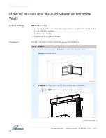
Combination Warmer
▪
Operator’s Manual
▪
MN-47424
▪
Rev 1
▪
4/21
29
Continued from previous page
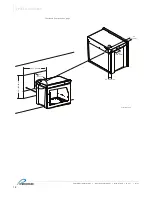
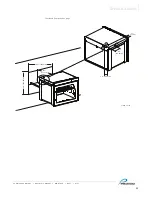
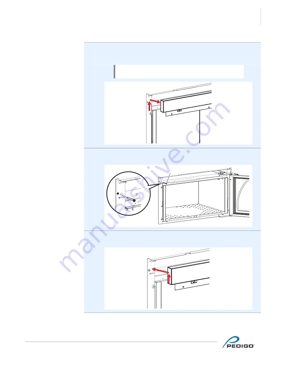
3.
Remove
the interface panel by pushing the assembly approximately 0.5”
(12.7mm) up, then pull forward at an angle to release the interface bends that
are locked by the tabs.
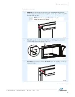
4.
Secure
the warmer to the wall using the two (2) self-tapping wall screws
(SC-47298)
b
and a #3 Phillips screwdriver.
5.
Re-install
the interface assembly.
Make sure
all of the tabs lock the interface
bends into place.
Continued on next page
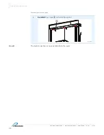
NOTE:
Make sure to support the interface panel to
reduce the strain on the cables.
EC-TS-011882
EC-TS-011885
b
EC-TS-011888
Содержание P-2420
Страница 4: ...FOREWORD Combination Warmer Operator s Manual MN 47424 Rev 1 4 21 4 This page intentionally left blank...
Страница 6: ...FOREWORD Combination Warmer Operator s Manual MN 47424 Rev 1 4 21 6 This page intentionally left blank...
Страница 10: ...SAFETY Combination Warmer Operator s Manual MN 47424 Rev 1 4 21 10 This page intentionally left blank...
Страница 24: ...SPECIFICATIONS Combination Warmer Operator s Manual MN 47424 Rev 1 4 21 24 This page intentionally left blank...
Страница 40: ...OPERATION Combination Warmer Operator s Manual MN 47424 Rev 1 4 21 40 This page intentionally left blank...
Страница 46: ...MAINTENANCE Combination Warmer Operator s Manual MN 47424 Rev 1 4 21 46 This page intentionally left blank...
Страница 54: ...TROUBLESHOOTING Combination Warmer Operator s Manual MN 47424 Rev 1 4 21 54 This page intentionally left blank...
Страница 60: ......
Страница 61: ......
Страница 62: ......
Страница 63: ......

