background image

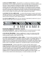
(8)   OUTPUT LEVEL: Adjusts the post-processing gain to make up for compression loss. It 
does not adjust the input level. The input levels should be set by the source equipment to 0 dBu
(1/4" jacks) or +4 dBu (XLR jacks) for best noise performance. The output level is monitored by an
LED meter to give a visual indication of signal strength.

(9)   GAIN REDUCTION METER: A twelve segment LED array that tells how much gain reduction
is being applied to the signal. If this meter is not active, there is no change to the input signal. It is
very useful for making adjustments, since the action of all controls is easily seen.

(10)  OUTPUT LEVEL METER: This is a peak indicating meter that is connected to the output jack.
The 0 dB point is 0 dBu for the 1/4" jacks and +4 dBu for the XLR jacks.

(11)  EXTERNAL SIDE CHAIN ENABLE: The side chain is actually an alternate loop inserted into
the detector path. This switch enables external processing. Frequency shaping can be applied for
de-essing (add a 2 kHz to 6 kHz bandpass filter) and rumble removal (add a 40 Hz to 120 Hz cut). If
there is nothing plugged into the side chain jack at the back of the unit, it connects the opposite
channel's signal to the detector and uses it for control, making this channel reduce amplitude (or
duck) when a signal is present on the other channel. Adjust the compressor controls for the desired
amount of action. When the side chain is active the LED will illuminate.

(12)  BYPASS: This is a hard wired bypass switch that connects the input jack directly to the output
jack (same type only). The 1/4" jacks are connected together and the XLR jacks are connected
together. Bypass will not function for 1/4" input to XLR output or XLR input to 1/4" output. When the
bypass is enabled the LED will illuminate.

(13)  STEREO LINK: If the compressor is to be used with stereo signals, the link switch should 
be pressed. It sums the RMS detector voltages together for an accurate representation of the two
levels, and locks the channels together to maintain the stereo image during compression. When
the link switch is pressed, all of channel A’s controls except the output level affect both channels.
The controls for channel B are disabled except its output level. As a reminder of this, the gain reduc-
tion meter for channel B is disconnected. The gain reduction meter for channel A is accurate for both
channels and should be used to monitor VCA activity. When the stereo link is enabled the LED will
illuminate

(14)  POWER SWITCH: Power is applied when this switch is pressed. As with all devices, the

power to external devices should be applied first, then the mixer and finally the power amp to
minimize turn on transients.

(15)  POWER LED  Indicates that AC mains power is connected and power switch is in the on 
position.

5

Содержание CEL-2

Страница 1: ...O W N E R S M A N U A L CEL 2 2 Channel Compressor Expander Limiter...

Страница 2: ...ci n Ce symbole est utilis pur indiquer l utilisateur la pr sence l int rieur de ce produit de tension non isol e dangereuse pouvant tre d intensit suffisante pour constituer un risque de choc lectriq...

Страница 3: ...gh when only mild compression low ratio is desired It has its own LED with a half second peak hold time to indicate when it has been activated Each section expander compressor or limiter can be set so...

Страница 4: ...compression It is the ratio of the input level to the output level A ratio of 4 1 signifies that the input level has increased four times as fast as the output the dynamic range is compressed by a fac...

Страница 5: ...sent on the other channel Adjust the compressor controls for the desired amount of action When the side chain is active the LED will illuminate 12 BYPASS This is a hard wired bypass switch that connec...

Страница 6: ...f the unbalanced output jack 17 is used the ring connection output of this jack is disconnected and it becomes an input only jack tip The nominal levels are 0 dBu 20 BALANCED INPUT XLR balanced input...

Страница 7: ...ages of the source between songs when the mics are not being used etc adjust the EXPANDER THRESHOLD CW until gain reduction is indicated a reduction of 12 dB is a good starting point Re adjust the EXP...

Страница 8: ...points 4 After all the settings are made adjust the OUTPUT LEVEL control for a 0 dB average on the output meter This control can also be used to change levels to match various inputs 4 dBu 0 dBu or 10...

Страница 9: ...dB 9 CEL 2 SPECIFICATIONS INPUT IMPEDANCE CONNECTOR XLR balanced 30k ohms XLR Pin 1 ground Pin 2 positive phase Pin 3 negative phase 1 4 Phone unbalanced 10k ohms 1 4 phone In Out tip input ring outp...

Страница 10: ...IN CNTRL V EXPAND THRESH RATIO COMPRESSTHRESH RATIO ATTACK RELEASE GAIN REDUCTION TO CHAN B LINK SW LIMIT THRESH TO CHAN B LINK SW RECTFIER RMS SC EXT TO CHAN B SIDE CHAIN JACK SIDE CHAIN BYPASS OUT I...

Страница 11: ...t Q 431f In CH A In CH B CS 800S SP 2G Mains In Out Q 431f Optional Unbalanced Output Optional Unbalanced Output Optional 1 4 Unbalanced Input Optional 1 4 Unbalanced Input Balanced Output Mains SRC 6...

Страница 12: ...imitador es un compresor de relaci n infinita que evita que la salida exceda el valor configurado mediante el control de umbral y s lo tiene una posici n de ajuste Es totalmente independiente de la co...

Страница 13: ...ente 2 RELACI N DEL EXPANSOR La relaci n del expansor se determina dividiendo el nivel de entrada por el nivel de salida Una relaci n de 1 3 significa que el nivel de salida cay tres veces m s r pido...

Страница 14: ...El nivel de salida se monitorea mediante un medidor con LED indicador que ofrece una indicaci n visual de la intensidad de la se al 9 MEDIDOR DE REDUCCI N DE GANANCIA La matriz de LED indicadores de d...

Страница 15: ...do el medidor de salida est configurado en 0 dB es de 4 dBu El terminal 2 es de fase positiva 17 SALIDA NO EQUILIBRADA Salida no equilibrada de 1 4 pulg Si se utiliza este enchufe hembra el enchufe he...

Страница 16: ...r todas las funciones Para esto lleve los controles a las posiciones que se indican a continuaci n UMBRAL EXTERNO M n desactivado RELACI N EXTERNA M n 1 1 1 UMBRAL DE COMPRESI N M x 20 dB RELACI N DE...

Страница 17: ...n de ganancia Este valor es una preferencia personal pero la reducci n de ganancia continua mayor que 9 dB especialmente cuando las relaciones son mayores ser a excesiva y crear a efectos de bombeo y...

Страница 18: ...esseur et peut tre utiliser pour emp cher des les pics du signal lors de l utilisation d une compression mod r e ratio faible Le limiteur poss de sa propre LED avec delay de une demi seconde pour indi...

Страница 19: ...e sortie Un taux de 4 1 signifie que le niveau d entr e a augment quatre fois plus vite que le niveau de sortie le registre dynamique est compress par un facteur 4 Si le taux est de 1 1 le niveau de s...

Страница 20: ...s illuminera 12 BYPASS V ritable bypass reliant l entr e d un canal la sortie du m me type correspondante Les Jacks sont alors connect s aux Jacks et les XLR aux XLR Le bypass ne fonctionne pas pour...

Страница 21: ...IEC permettant l alimentation du CEL 2 L utilisation d une ligne secteur au voltage inappropri peut causer des dommages votre appareil consultez les tensions d alimentation inscrites sur l appareil UT...

Страница 22: ...r s rendant les transitions plus discr tes 3 Pour la compression des voix r glez le taux de compression 4 1 des valeurs de 2 1 6 1 sont commun ment utilis es et ajustez le seuil jusqu ce que la r duct...

Страница 23: ...ession Low Ratio erw nscht wird Er verf gt ber eine eigene LED Anzeige mit einer Peak Haltezeit von einer halben Sekunde um seine Aktivierung anzuzeigen Jede Sektion Expander Kompressor oder Limiter l...

Страница 24: ...menge Hierbei handelt es sich um das Verh ltnis zwischen Eingangs und Ausgangspegel Ein Verh ltnis von 4 1 deutet an da der Eingangspegel gegen ber dem Ausgangspegel 4 mal so schnell angestiegen ist d...

Страница 25: ...und bewirkt da dieser Kanal die Amplitude reduziert wenn am anderen Kanal ein Signal anliegt Justieren Sie die Kompressorregler auf die gew nschte Aktionsgr e Bei aktivierter Side Chain leuchtet die L...

Страница 26: ...ie Ring Verbindung Output dieser Buchse unterbrochen und wechselt zu einer nur Eingangsbuchse Spitze Tip Die Nominalpegel entsprechen 0dBu 20 SYMMETRISCHER EINGANG Symmetrischer XLR Eingang f r 4dBu n...

Страница 27: ...enn unerw nscht Vielleicht m ssen Sie zur ckgehen und den Schwellwert nach nderung des Ratio neu justieren da der Soft Knee Schaltkreis im Bereich kleinerer Verh ltnisse Ratios effektiver arbeitet und...

Страница 28: ...28 NOTES...

Страница 29: ...29 NOTES...

Страница 30: ...ay the return shipping charges How To Get Warranty Service 1 Take the defective item and your sales receipt or other proof of date of purchase to your Authorized Peavey Dealer or Authorized Peavey Ser...

Страница 31: ...ld with the apparatus When a cart is used use caution when moving the cart apparatus combination to avoid injury from tip over 13 Unplug this apparatus during lightning storms or when unused for long...

Страница 32: ...ures and specifications subject to change without notice Peavey Electronics Corporation 711 A Street Meridian MS 39301 601 483 5365 FAX 601 486 1278 www peavey com 1998 Printed in the U S A 11 98 8030...

Отзывы: