background image

Configuration

Page 31

Peavey Electronics Corp

Setting the Audio Bundle

Now that you have established communications between the MediaMatrix software and the CAB

16 hardware, you will need

to prepare the network to pass audio.  CobraNet

is a powerful protocol that allows you to pass up to 64 channels (32 in by 32

out) of digital audio per MediaMatrix MM-DSP-cn Digital Audio Processing card to a practically unlimited number of CAB 8
and CAB 16 Series products.

The first order of business is to plan your system out.  Good system design and careful planning of your resources, routing, pro-
cessing and distribution requirements will ensure a seamless installation of the audio network.  You should have a systemic
method of assigning your hardware IDs and your 

Audio Bundles

.  For example, you may want to number all incoming audio as

odd numbered bundles, and outgoing audio as even numbered bundles.  You may want to create a numbering scheme that syn-
chronizes the 

Hardware Base Address

IDs with the 

Audio Bundles

so that there is some consistency in the way your system

is identified.

Remember that in CobraNet, audio travels across the network in a 

Bundle*.

This 

Bundle 

includes eight digital audio 

chan-

nels.  

These eight channels get into, and out of, the MediaMatrix processing engine via the CobraNet 

IInnppuutt B

Blloocckk

and 

O

Ouuttppuutt

B

Blloocckk

.  If this is not clear to you, please go back and review the section entitled, “Hardware & Software Devices” and “The Test

View” earlier in this manual.

In order to get audio into the system, we have to set an 

Audio

Bundle 

number on a CobraNet 

IInnppuutt B

Blloocckk.

The number is a nor-

mal number and the range is OFF to 32,767.  For switched net-
works, the number must be 256 or higher*. You do not need to be
concerned with additional zeros or other syntax.  The number you
set is what you get.  To set the 

Bundle Number, 

place your 

C

Coonnttrrooll

M

Mooddee

cursor over the pink box next to the 

Bundle 

label in the

CAB control device and type a number, any number, into the box.
Alternately, you may also 

ggeessttuurree

the number by holding down the

mouse button and dragging the control until the number you want

appears in the box.  (Refer to
the MediaMatrix Help for
information on making this
control gesturable.)

To complete the process, this
same 

Bundle Number 

must also be set on the corresponding CAB 16 unit for each group of

eight channels.  In order to get audio from a given CobraNet 

IInnppuutt  or O

Ouuttppuutt B

Blloocckk

, the num-

bers must match in the blocks and the 

CAB 16  Taxi Device

.  The process for setting the

Bundle Number

in the 

Taxi Device

is the same, and you must be in 

C

Coonnttrrooll M

Mooddee.  

It is

important to note that there are two 

Bundle Numbers

on CAB 16 products, one for each

set of eight audio channels.

That is pretty much it as far as setting up the CAB 16 to communicate and pass audio on the CobraNet network.  There are
many  additional variables in larger systems, but this is the basic configuration.  What is very important to understand is the
relationship of the CAB device, the 

Taxi

, and the CobraNet audio transport.  If audio inputs are coming in on a CAB 16i and

assigned to CobraNet 

Bundle 285

, then a CobraNet 

IInnppuutt B

Blloocckk

must be set to 

Audio Bundle 285

as well.  

*NOTE:

The 

Bundle Numbers

referred to in this section assume the use of a switched (Unicast) network.  Although it is pos-

sible, we do not recommend the use of hub-based (Multicast) networks with MediaMatrix systems.  For more information on
using a Multicast network with CobraNet, please refer to page 37, Additional Information, and see the article on “Bundle
Assignments in CobraNet Systems”. 

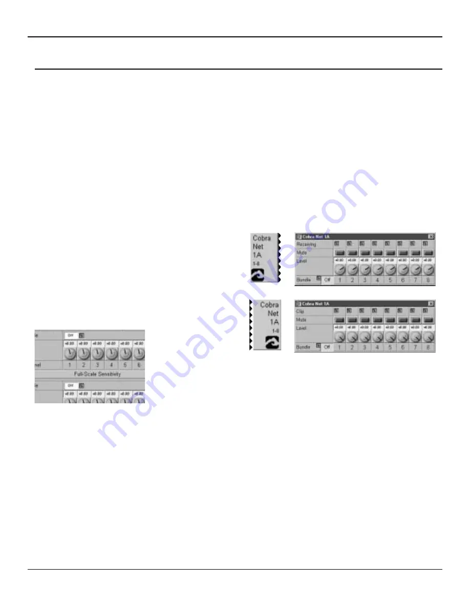
Fig. 18, CobraNet Input and Output Controls  (Bundle Numbers in the
OFF position)

Fig. 19, CAB Device Audio Bundle
Number controls shown in the OFF posi-
tion.

Содержание CAB 16i

Страница 1: ...CAB 16 Series CobraNet Audio Bridge CAB 16i CAB 16o CAB 16d User Manual ...

Страница 2: ...bole est utilisé dans ce manuel pour indiquer à l utilisateur la présence d une tension dangereuse pouvant être d amplitude suffisante pour constituer un risque de choc électrique Ce symbole est utilisé dans ce manuel pour indiquer à l utilisateur qu il ou qu elle trouvera d importantes instructions concernant l utilisation et l entretien de l appareil dans le paragraphe signalé ATTENTION Risques ...

Страница 3: ...e or will be stored If this product is to be mounted in an equipment rack install rear support if required by the rack manufacturer Care should be taken to ensure that the installation is clear of possible sources of contamination Make sure that the product s ventilation openings are not exposed to possible sources of liquid gases or other contaminants This product should be inspected by a qualifi...

Страница 4: ...ing 32 33 Testing Testing Digital Style 34 35 Tech Support Warranty Registration 36 CAB 16i 12 CAB 16i Front Panel 16 CobraNet 22 Audio 23 CAT 5 cable is your friend 26 27 Linking 28 CAB 16i Rear Panel 17 CAB 16o Front Panel 18 CAB 16o Rear Panel 19 CAB 16d Front Panel 20 CAB 16d Rear Panel 21 CAB 16o 13 CAB 16d 14 15 CAB 16 Series User Manual Table of Contents Additional Resources 37 Specificatio...

Страница 5: ...e Figure 14 29 Hardware Base Address Switches Figure 16 30 Hardware Software Addressing Controls Figure 17 30 CobraNet Input and Output Controls Bundle Numbers in the OFF position Figure 18 31 CAB Device Audio Bundle Number controls shown in the OFF position Figure 19 31 Test Configuration CAB 16i CAB 16o 32 33 Test Configuration CAB 16d 34 35 Illustrations CAB 16d Link Connection Example Figure 1...

Страница 6: ...stallation or upgrading firmware within the CAB 16 is not covered in this manual Several associated products are required to complete a working system using the CAB 16 This manual frequently makes refer ence to these other products but does not provide specific configuration or installation information on them Please refer to the manuals for these products for information Every product both Peavey...

Страница 7: ...ve a comment about this manual or would like to make a suggestion please write to Peavey Electronics Corp Architectural Acoustics Division 711 A St Meridian MS 39301 Thank you again for using Peavey What s In The Box The CAB 16 Series products are packaged in a single container This contain er includes the following items 1 CAB 16i CAB 16o or CAB 16d CobraNet Audio Bridge 1 IEC removable power sup...

Страница 8: ...e interface make it per fect for many applications where simple audio transport is required Among the many applications the CAB 16 Series was designed for include Theme Parks Presentation Rooms Board Rooms Courtrooms Auditorium Cafetorium Lecture Hall Sound Reinforcement Meeting Rooms Convention Centers Paging Background Music Retail Spaces Restaurant Bar Sound The CAB 16 Series is a prefect choic...

Страница 9: ...ints and defec tive terminations To successfully install your new CAB 16 Series product and perform the testing examples contained in this manual you will need the following com ponents A MediaMatrix MiniFrame 208nt cn or MM 760nt MM 960nt or MM 980nt Mainframe MWare 3 1 2 or later software PC Monitor mouse and keyboard At least 1 MM DSP cn CobraNet DPU card for MediaMatrix At least 1 CAB 16i and ...

Страница 10: ...as the Taxi since it s a yellow CAB get it The figure below shows the relationship between the Taxi its control panel and the actual CAB hardware The second half of this equation as mentioned above is the audio transport This transport is the CobraNet network that car ries audio from one location to another Within MediaMatrix this is represented by a block with wire nodes on it that repre sent the...

Страница 11: ...udio path within the MediaMatrix system The blocks labeled CAB the yellow Taxi represent the actual CAB hardware There must be one of these for each corresponding hardware piece The hardware via its control panel can be assigned to any network audio channel called a bundle This bundle is also assigned in the CobraNet transport block It is this bundle assignment that gets the audio from the CAB s a...

Страница 12: ...vice for which the CAB will transport audio The LED is ON when the CAB 16i is receiving the specified network bundle Each CAB 16i can receive two separate audio bundles GAIN Software control of the CAB 16i s analog gain stage Gesturable from the knob or the digital window located just above each knob The range is 95 5 dB to 30 5 dB FULL SCALE SENSITIVITY BLOCK When clicked upon this block opens an...

Страница 13: ... the specified network bundle Each CAB 16o can transmit send two separate audio bundles MUTE This single button will mute all audio outputs in the digital domain This button is independent of the output GAIN control GAIN Software control of the CAB 16o s analog output stage Gesturable from the knob or the digital window located just above each knob The range is 95 5 dB to 30 5 dB FULL SCALE SENSIT...

Страница 14: ...e CAB 16d DISABLE OUTPUTS This switch turns off the AES transmitters so that no valid AES data is output from the box This is different from Muting outputs in that muting stops audio data but maintains valid AES output BUNDLE User defined number that assigns eight audio channels to a CobraNet network bundle The range is OFF to 32 767 For switched networks the number must be 256 or higher This numb...

Страница 15: ...e of the incoming AES data stream This is the sam ple rate of the input signal before conversion LOCK Indicates the CAB has locked to the incoming audio data stream COPY The copy bit on the AES audio stream is set AUDIO Indicates that valid audio data has been detected on the inputs OUTPUT CHANNEL DISABLE This switch turns off the AES transmitters so that no valid AES data is output from the box T...

Страница 16: ... 16 from the CobraNet network FAULT LED Illumination of the Fault indicator indicates detection of an unexpected condi tion within the CobraNet interface Some fault conditions will also light the RX Error and or TX Error indicators to give more specific indication if the unexpected condition is in the receive or transmit processes The errors are reported by a series of flashes See page 37 for help...

Страница 17: ...ceives link data from other CAB units or third party synchronization products COBRANET NETWORK I O RJ 45 connector provides interface to the CobraNet audio network This connection is required to pass audio with the CAB 16 RS 485 PORT Two two wire half duplex RS 485 connections on removable Euro connec tors Each connector is internally wired together for convenient busing of adjacent units AUDIO IN...

Страница 18: ... 16 from the CobraNet network FAULT LED Illumination of the Fault indicator indicates detection of an unexpected condi tion within the CobraNet interface Some fault conditions will also light the RX Error and or TX Error indicators to give more specific indication if the unexpected condition is in the receive or transmit processes The errors are reported by a series of flashes See page 37 for help...

Страница 19: ...eives link data from other CAB units or third party synchronization products COBRANET NETWORK I O RJ 45 connector provides interface to the CobraNet audio network This connection is required to pass audio with the CAB 16 RS 485 PORT Two two wire half duplex RS 485 connections on removable Euro connec tors Each connector is internally wired together for convenient busing of adjacent units AUDIO OUT...

Страница 20: ...onto the CobraNet network See Appendix Error Reporting RX ERROR LED Indicates that an error occurred while receiving data into the CAB 16 from the CobraNet network See Appendix Error Reporting FAULT LED Illumination of the Fault indicator indicates detection of an unexpected condi tion within the CobraNet interface Some fault conditions will also light the RX Error and or TX Error indicators to gi...

Страница 21: ...t audio network This connection is required to pass audio with the CAB 16 RS 485 PORT Two two wire half duplex RS 485 connections on removable Euro connec tors Each connector is internally wired together for convenient busing of adjacent units AUDIO INPUT CONNECTORS Balanced three wire digital AES3 audio input connec tions on removable Euro connectors This illustration shows the connector header o...

Страница 22: ...or more MM DSP cn cards within the MediaMatrix frame The example below is the most basic configuration Large systems on managed networks can get very complex Please don t get ahead of yourself here You need to be able to make this configuration work first Fig 4 Typical Network Connections Fig 5 Direct Connection Example Standard CAT5 Cable Crossover CAT5 Cable See p 26 27 100 Base T Network Switch...

Страница 23: ...ve Negative Shield SH Standard audio cable From RS 485 Device To Next RS 485 Device Plug this here RS 485 Connections The third connection is the CAB Series RS 485 Serial Port All CAB Series products include this powerful feature that enables you to bridge serial data between CAB locations on the CobraNet network You can think of this as a kind of sub network that travels across the CobraNet infra...

Страница 24: ... still the same only the transport media has changed To make sure that your S PDIF audio signals work correctly with the CAB 16d it is required that these circuits be installed between the S PDIF devices and the CAB 16d An important fact of digital audio transport is that the wire type is signifi cantly different than wire used for terminating analog audio circuits AES3 uses symmetrical connection...

Страница 25: ...o a CAB 16d input requires that the output level and impedance of the S PDIF source be matched to the CAB 16d s input circuit The following circuit provides attenuation from the source through one in line 51 Ohm resistor on the positive leg of the signal The impedance matching is accomplished by using a 150 Ohm resis tor across both legs of the S PDIF source signal NOTE A jumper is required betwee...

Страница 26: ...l pairs be terminated and that the conductors be twisted together in pairs The illustrations should give you the basics for getting your cables and your audio system up and running Although pre made molded style cables are preferred they are usually impractical since your cabling route distance and locations are based on the jobsite conditions and not your test bench Additionally you will need rac...

Страница 27: ...hite w blue stripe Blue w white stripe White w orange stripe Orange w white stripe White w green stripe Green w white stripe White w brown stripe Brown w white stripe Conductor 1 1 2 2 3 3 4 4 Wire Pair 5 4 1 3 x over 2 6 x over 3 1 x over 6 2 x over 7 8 Connector Pin Not used Not used TX TX RX RX Not used Not used Function TX Pair Pins 1 8 RX Pair Remember for ethernet the BLUE and BROWN pairs ar...

Страница 28: ...to work properly both units must be config ured to use the same Audio Bundle number p 30 31 As long as the primary unit is powered on and it sees a good CobraNet connection Ethernet link status good and it has not experienced a fault it generates a signal from its LINK OUT connector which inhibits the secondary unit from tak ing over until there is a failure or fault The action of the switch over ...

Страница 29: ...n active distribution method must be used or ideally redundant digital audio should be sourced independently as shown in this example NOTE Using the Link Connectors for creating redundancy is limited to dual CAB units Where addition al CABs are used additional redun dant units must also be added CAB 16o Primary CAB 16o Secondary or Slave Audio Output CAB 16d Primary Redundant Audio Inputs CAB 16d ...

Страница 30: ...et the same address within the MediaMatrix software using the yellow CAB device or as I mentioned earli er the Taxi The Taxi device represents the actual hardware and there must be one Taxi for each physical CAB 16 In addi tion to this hardware address setting the Taxi device includes the CAB 16 s analog controls and the CobraNet Bundle assign ment control for the CAB 16 s audio network channel Mo...

Страница 31: ... number you set is what you get To set the Bundle Number place your C Co on nt tr ro ol l M Mo od de e cursor over the pink box next to the Bundle label in the CAB control device and type a number any number into the box Alternately you may also g ge es st tu ur re e the number by holding down the mouse button and dragging the control until the number you want appears in the box Refer to the Media...

Страница 32: ...ear Listen for dropouts distortion and other undesirable noises If you hear any of this especially dropouts you ve got a problem Also take note of the action of the front panel status LEDs There should be lots of green and no red Hardware Base Address assigned to 0c92 CAB Audio Bundle set to 285 at the Taxi AND the CobraNet input block The Input Side a CAB 16i The Tunes The Processing a MediaMatri...

Страница 33: ...receive Audio Bundle 12 and assigned a HardWare Base Address of 221f both on its front panel and the corresponding Taxi device The audio is then output from the CAB 16o s analog outputs From there it is amplified to a set of cool high quality 2 way loudspeakers The result Tunes This simple view file is what lives inside the MediaMatrix Mainframe It is very simple input process and output In this e...

Страница 34: ...gital audio device within the CAB 16d s Taxi device In this example we are showing audio sourced from digital sources a CD player and DAT recorder both with AES or S PDIF inputs and outputs The audio signal is in the digital domain throughout the signal flow Hardware Base Address assigned to 0c92 The Input Side Play Tunes MediaMatrix MainFrame shown with 1 MM DSP cn and 1 MM DSP cards AES3 or S PD...

Страница 35: ...Taxi AND the CobraNet input block AES3 or S PDIF Digital Audio Input Testing Page 35 Peavey Electronics Corp The Output Side Hardware Base Address assigned to 221f CAT5 Cable typ Record Tunes The Output Side The Input Side The Processing ...

Страница 36: ...from other audio professionals around the world You can also get help by sending us an e mail or posting a request on the message board Finally if you still cannot get the information you need don t hesitate to call us We have extensive phone support services and will be happy to assist you The contact information for the Architectural Acoustics Division is shown below Peavey Electronics Corp Arch...

Страница 37: ...repeater htm diameter CobraNet Technology Richard Zweibel Kevin Gross http peakaudio com cobranet papers technology htm Digital Synchronization in CobraNet Systems http peakaudio com cobranet papers sync html Switched Network Design Configuration http peakaudio com cobranet examples htmhttp peaka udio com cobranet examples htm CobraNet on Switched Networks http peakaudio com cobranet switched htm ...

Страница 38: ... signal with 20 dB head room 108 dB 110 dBA 22 kHz filter band width measurement 55 dB typ Any gain setting 100 dB 20 20 kHz measured between channel pairs 1 2 3 4 15 16 30 24 18 12 dBu Less than 0 5 dB error between settings N A 97 5 to 30 5 dB 1 2 dB steps 0 05 dB maximum error 9 5k Ohms minimum balanced circuit value at any setting 16 peak reading headroom LED meters analog level at input of A ...

Страница 39: ... time 6 nS 110 Ohm load Audio Transmission Quantization Via CobraNet 20 or 24 bit CobraNet truncates to 20 bits unless used in reduced channels mode Digital Processing 24 bit DSP s 56 bit accumulators Sample Rate 48 kHz Sample Rate Conversion Range 32 kHz 96 kHz Sample rate convertor locks to any sample rate within conversion range presented at the AES EBU inputs CobraNet System Latency 5 33 ms ea...

Страница 40: ... Authorized Peavey Dealer or Authorized Peavey Service Center OR 2 Ship the defective item prepaid to Peavey Electronics Corporation International Service Center 412 Highway 11 80 East Meridian MS 39301 or Peavey Canada Ltd 95 Shields Court Markham Ontario Canada L3R 9T5 Include a detailed description of the problem together with a copy of your sales receipt or other proof of date of purchase as e...

Страница 41: ...tions subject to change without notice A product of Peavey Electronics Corporation 711 A Street Meridian MS 39301 USA 601 483 5376 FAX 601 486 1678 http aa peavey com Copyright 2000 All Rights Reserved Printed in USA 4 2000 ...

Отзывы: