Installation of Host Computer and Peripherals
Network Installation
3-10
Installation Guide for the OpScan iNSIGHT 70 Scanner
Board/Connector Relationship
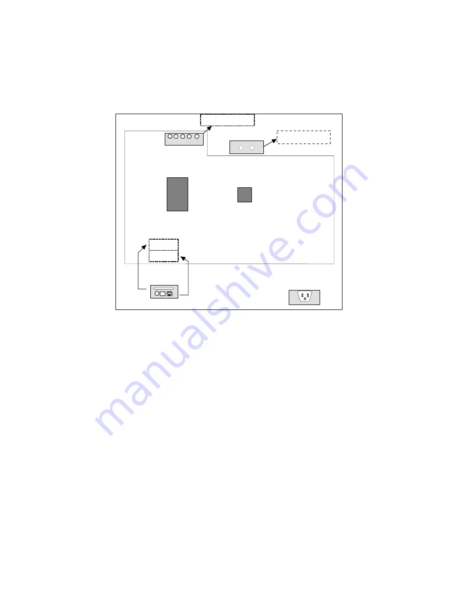
Figure 3-4 illustrates the relationship between PC boards attached to the bulkhead
inside the cabinet and the connectors on the exterior surface of the cabinet in a
network configuration.
Figure 3-4
Network, Board/Connector Locations
MONITOR
KEMCON
KEYBOARD MOUSE
CAMERA
CONTROLLER
BOARD
SCANNER
CONTROLLER
MAIN BOARD
PRTCON
NETCOM
INPUT POWER
No Board Required for
Monitor (Pass Through)
LINE PRINTER
NETWORK
Содержание OpScan iNSIGHT 70
Страница 1: ...Installation Guide for the OpScan iNSIGHT 70 Scanner...
Страница 2: ......
Страница 5: ...iii Revision Log 203 737 002 Tab Date Description 5 05 Manual Released...
Страница 6: ...iv Installation Guide for the OpScan iNSIGHT 70 Scanner...
Страница 16: ...Scanner Overview Customer Support 1 6 Installation Guide for the OpScan iNSIGHT 70 Scanner...
Страница 47: ......
Страница 48: ...203 737 002...


