background image

Continuity 

 
Model 

Audible Threshold  

Test current 

P 3355 

< 150 

Ω 

<0,3    mA 

P 3360 

<   35 

Ω 

< 0,35 mA 

Overload protection: 

600 V DC/AC

rms 


Diode Test 


Model 

Test current 

Open circuit 

voltage 

P 3355 

0,3 mA 

1,5 V 

P 3360 

0,9 mA 

2,8 V 

Overload protection: 

600 V DC/AC

rms 


-45- 

Содержание 3355

Страница 1: ...PeakTech 3355 3360 Bedienungsanleitung operation manual Mode d emploi Istruzioni per l uso Manual de instrucciones Digital Multimeter Multimètre digital Multimetro digitale Multímetro digital ...

Страница 2: ...T IV CAT IV Units and installations which are supplied overhead lines which are stand in a risk of persuade of a lightning i e main switches on current input over voltage diverter current use counter To ensure safe operation of the equipment and eliminate the danger of serious injury due to short circuits arcing the following safety precautions must be observed Damages resulting from failure to ob...

Страница 3: ...ent measurements with the leads connected to the V Ω terminals of the equipment Check test leads and probes for faulty insulation or bare wires before connection to the equipment To avoid electric shock do not operate this product in wet or damp conditions Conduct measuring works only in dry clothing and rubber shoes i e on isolating mats Never touch the tips of the test leads or probe Comply with...

Страница 4: ...or indoor use only Do not operate the meter before the cabinet has been closed and screwed safely as terminal can carry voltage Do not store the meter in a place of explosive inflammable substances Do not modify the equipment in any way Do not place the equipment face down on any table or work bench to prevent damaging the controls at the front Opening the equipment and service and repair work mus...

Страница 5: ...C or VDC This symbol adjacent to one or more terminals identifies them as being associated with ranges that may in normal use be subjected to particulary hazardous voltages For maximum safety thermometer and its test leads should not be handled when these terminals are energized Indicates protection class II double insulation IP67 Dust and waterproof µA The maximum current that can measure with th...

Страница 6: ...nd therefore the touchable and conductive part of the probes have only max 4mm of length CAUTION This CAUTION symbol indicates a potentially hazardous situation which if not avoided may result in minor or moderate injury or damage to the product or other property 2 Technical Data 2 1 Specifications Display P 3355 26 mm 3 digit 4000 counts with automatic polarity indication and backlight P 3360 19 ...

Страница 7: ... only P 3360 Overload protection on all ranges Operating Temperature 41 F to 104 F 5 C to 40 C Storage Temperature 4 F to 140 F 20 60 C Accuracy Temperature 64 F to 82 F 18 C to 28 C to maintain guaranteed accuracy Relative Humidity 80 operating Dimensions W x H x D 85 x 185 x 55 mm Weight approx 400 g Power source 9 V battery Neda 1604 Accessories supplied Operation manual test leads socket seals...

Страница 8: ...100 mV 0 1 rdg 5 dgt Overload protection 1000V AC DCrms Input Impedance P 3355 7 8 MΩ P 3360 10 MΩ AC Volts Model Range Resolution Accuracy P 3355 400 mV 100 µV 1 0 rdg 5 dgt 4 V 1 mV 1 0 rdg 3 dgt 40 V 10 mV 400 V 100 mV 1000 V 1 V P 3360 400 mV 100 µV 1 0 rdg 5 dgt 4 V 1 mV 1 0 v M 3 dgt 40 V 10 mV 400 V 100 mV 1000 V 1 V Overload protection 1000V AC DCrms Input Impedance P 3355 7 8 MΩ P 3360 3 ...

Страница 9: ... 5A 1000V and 10A 1000V Max Input 400mA DC on mA ranges and 10A on A range AC current Model Range Resolution Accuracy P 3355 400 µA 0 1 µA 1 5 rdg 5 dgt 4000 µA 1 µA 40 mA 10 µA 1 8 rdg 5 dgt 400 mA 100 µA 10 A 10 mA 3 0 rdg 7 dgt P 3360 400 µA 0 1 µA 4000 µA 1 µA 40 mA 10 µA 1 5 rdg 3 dgt 400 mA 100 µA 10 A 10 mA Overload protection 0 5A 1000V and 10A 1000V Max input 400mA DC on mA Range and 10A ...

Страница 10: ... Ω 400 kΩ 10 Ω 4 MΩ 100 Ω 40 MΩ 1 kΩ 2 0 rdg 10 dgt Overload protection 600 V DC ACrms Capacitance Model Range Resolution Accuracy P 3355 4 nF 1 pF 5 0 rdg 20 dgt 40 nF 10 pF 5 0 rdg 7 dgt 400 nF 100 pF 3 0 rdg 5 dgt 4 µF 1 nF 40 µF 10 nF 100 µF 100 nF 5 0 rdg 5 dgt P 3360 40 nF 1 pF 3 5 rdg 40 dgt 400 nF 10 pF 4 µF 100 pF 3 5 rdg 10 dgt 40 µF 1 nF 400 µF 10 nF 4000 µF 100 nF 5 0 rdg 10 dgt 40 mF ...

Страница 11: ...kHz 10 Hz 1000 kHz 100 Hz 10 MHz 1 kHz 1 5 rdg 4dgt P 3360 40 Hz 1 mHz 400 Hz 10 mHz 0 1 rdg 1 dgt 4 kHz 100 mHz 40 kHz 1 Hz 400 kHz 10 Hz 4 MHz 100 Hz 40 MHz 1 kHz 100 MHz 10 kHz not specified Overload protection 600 V DC ACrms Sensitivity 0 5V RMS at 1MHz 3V RMS at 1MHz P 3355 Sensitivity 0 8V RMS at 100kHz 5V RMS at 100kHz P 3360 43 ...

Страница 12: ... 50 dgt 0 mA 25 4 mA 0 20 mA 100 24 mA 125 Pulse width 100 µs 100 ms Frequency 5Hz 150kHz Sensitivity 0 5Vrms Overload protection 600 V DC ACrms Temperature Model Range Resolution Accuracy P 3355 20 760 C 1 C 3 0 rdg 3 0 C 4 1400 F 1 F 3 0 rdg 3 0 F P 3360 50 1000 C 1 C 1 0 rdg 2 5 C 58 1832 F 1 F 1 0 rdg 4 5 F Overload protection 600 V DC ACrms Temperature Accuracy Probe accuracy not included 44 ...

Страница 13: ...Threshold Test current P 3355 150 Ω 0 3 mA P 3360 35 Ω 0 35 mA Overload protection 600 V DC ACrms Diode Test Model Test current Open circuit voltage P 3355 0 3 mA 1 5 V P 3360 0 9 mA 2 8 V Overload protection 600 V DC ACrms 45 ...

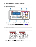
Страница 14: ...tton 4 Mode pushbutton 5 Function switch 6 µA mA 10 A positive input jack 7 COM negative input jack 8 Positive input jack for voltage Hz Duty cycle Ohms Diode Continuity Capacitance and temperature measurements 9 Data Hold and Backlight pushbutton 10 PEAK button 11 MIN MAX button 47 ...

Страница 15: ...nheit C Temperature in Centigrade MAX Maximum MIN Minimum PEAK Peak hold V voltage REL Relative AUTO Autoranging HOLD Display hold 4 Operating instructions Warning Risk of electrocution High voltage circuits both AC and DC are very dangerous and should be measured with great care 1 Always push the power pushbutton to the OFF position when the meter is not in use This meter has Auto OFF that automa...

Страница 16: ...tomatically selects the best range for the measurements being made and is generally the best mode for most measurements For measurement situations requiring that the range be manually held perform the following 1 Press the RANGE button The AUTO indicator will extinguish and the currently selected range will be held 2 Press the RANGE button to step through the available ranges until you select the ...

Страница 17: ...en power on the meter The display shows APO d To activate the APO function the meter must be power off Then power on the meter 5 Measuring 5 1 Relative The relative measurement feature allows you to make measurements relative to a stored reference value A reference voltage current etc can be stored and measurements made in comparison to that value The displayed value is the difference between the ...

Страница 18: ... OFF operations that can damage the meter 1 Set the function switch to the V position 2 If AC appears in the display press the MODE pushbutton until DC appears in the display 3 Insert the black test lead banana plug into the negative COM jack and the red test lead banana plug into the positive V jack 4 Touch the test probe tips to the circuit under test Be sure to observe the correct polarity red ...

Страница 19: ...ge voltage surges may occur during the ON or OFF operations that can damage the meter 1 Set the function switch to the V position 2 Press the MODE button until AC appears in the display 3 Insert the black test lead banana plug into the negative COM jack and the red test lead banana plug into the positive V jack 4 Touch the test probe tips to the circuit under test 5 Read the voltage in the display...

Страница 20: ...e of the circuit and touch the red test probe tip to the positive side of the circuit 8 Apply power to the circuit 9 Read the current in the display The display will indicate the proper decimal point value and symbol 5 6 AC current measurements Warning To avoid electric shock do not measure AC current on any circuit whose voltage exceeds 250 V AC 1 Insert the black test lead banana plug into the n...

Страница 21: ...e the proper decimal point value and symbol 5 7 Resistance measurements Warning To avoid electric shock disconnect power to the unit under test and discharge all capacitors before taking any resistance measurements Remove the batteries and unplug the line cords 1 Set the function switch to the OHM position 2 Insert the black test lead banana jack into the negative COM jack and the red test lead ba...

Страница 22: ...he OHM position 2 Insert the black test lead banana jack into the negative COM jack and the red test lead banana plug into the positive Ω jack 3 Press the MODE push button until the symbol appears in the display 4 Touch the test probe tips to the circuit or wire you wish to check 5 If the resistance is less than 150 ohms P 3355 or 35 ohms P 3360 the audible signal will sound The display will also ...

Страница 23: ...good B If both readings are OL the device is open C If both readings are very small or 0 the device is shorted Note The value indicated in the display during the diode check is the forward voltage 5 10 Frequency Duty cycle measurement 1 Set the function switch to the Hz position 2 Insert the black test lead banana jack into the negative COM jack and the red test lead banana plug into the positive ...

Страница 24: ...perature measurements Warning To avoid electric shock disconnect both test probes from any source of voltage before making a temperature measurement Insert the adapter in the input socket for temperature measurements Insert the K type thermocouple into the temperature socket making sure to observe the correct polarity Touch the temperature probe head to the part whose temperature you wish to measu...

Страница 25: ...re or other hazard replace only with fuse of the specified voltage and current ratings Follow these steps to replace the fuse 1 Press ON OFF button to turn the meter off and disconnect the test probes 2 Remove the Battery cover screws B and the battery 3 Remover the back cover by unscrewing the 6 screws A 4 Remove the blown fuse Use only a fuse with the proper size and value 500mA 1000V 6 3x32mm o...

Страница 26: ...formed 1 Keep the meter dry If it gets wet wipe it off 2 Use and store the meter in normal temperatures Temperature extremes can shorten the life of the electronic parts and distort or melt plastic parts 3 Handle the meter gently and carefully Dropping it can damage the electronic parts or the case 4 Keep the meter clean Wipe the case occasionally with a damp cloth Do not use chemicals cleaning so...

Страница 27: ...oesn t operate check to be sure that both ends of the fuse are properly installed 9 Replacing the battery Warning To avoid electric shock disconnect the test leads from any source of voltage before removing the back cover or the battery fuse door 1 Disconnect the test leads from the meter 2 Open the battery fuse door by loosening one screw on the battery fuse door using a screw driver 3 Clip the n...

Страница 28: ...ustomers of the following Please dispose of old batteries at a council collection point or return them to a local shop at no cost The disposal in domestic refuse is strictly forbidden according to the Battery Regulations You can return used batteries obtained from us at no charge at the address on the last side in this manual or by posting with sufficient stamps Batteries which contain harmful sub...

Страница 29: ...n permission of the publisher This manual considers the latest technical knowing Technical changings which are in the interest of progress reserved We herewith confirm that the units are calibrated by the factory according to the specifications as per the technical specifications We recommend to calibrate the unit again after 1 year PeakTech 01 2013 Ho Pt 62 ...

Отзывы: