background image


WaveStar

®


Color Monitor 

Setup and Operation


Ctrl Nr: PM375103 

Revision: 003 

Содержание PM375103

Страница 1: ...WaveStar Color Monitor Setup and Operation Ctrl Nr PM375103 Revision 003 ...

Страница 2: ...dicorp com service pdicorp com WaveStar Color Monitor Setup and Operation Ctrl Nr PM375103 Revision 003 Release Date December 2017 2017 by Power Distribution Inc All rights reserved Cover Photo WaveStar Color Monitor Home Screen PDI JCOMM Quad Wye ToughRail Technology and WaveStar are registered trademarks of Power Distribution Inc All other trademarks are held by their respective owners Power Dis...

Страница 3: ...and Termination 12 2 4 Ethernet Cables 12 2 5 Customer Modbus RTU Connections 12 2 5 1 Power Distribution Unit PDU 13 2 5 1 Remote Power Panel RPP 14 2 5 1 JCOMM 14 2 6 Modbus Addressing 15 2 7 Communicating with the Monitor Commands and Replies 16 2 7 1 Modbus Commands and Replies 16 2 7 2 Limit on Open Sockets 16 2 7 3 SNMP Commands 16 3 Setup Monitor and Network 17 3 1 SETUP Miscellaneous Param...

Страница 4: ...5 6 2 Alarm Screen and Alarm List 35 6 3 Alarms by Device Type 37 6 3 1 Color Monitor Alarms 37 6 3 2 PDU Alarms 37 6 3 3 Enhanced Subfeeds 39 6 3 4 BCMS Panelboard Typical Alarms 40 6 4 Troubleshooting 40 7 Web Pages 42 Glossary 46 Bibliography 47 Appendix Color Monitor Backpanel 48 Tables Table 1 Pin Out for Modbus Headers 11 Figures Figure 1 WaveStar Color Monitor Installed in a JCOMM 7 Figure ...

Страница 5: ...ds 25 Figure 21 Settings BCMS IEC 26 Figure 22 Readings PDU 27 Figure 23 Readings Enhanced Subfeeds ESF Part 1 28 Figure 24 Readings Enhanced Subfeeds ESF Part 2 29 Figure 25 Readings BCMS Normal 30 Figure 26 Readings BCMS KWH Part 1 31 Figure 27 Readings BCMS KWH Part 2 32 Figure 28 Readings BCMS CB Two Subfeeds 33 Figure 29 Readings BCMS IEC Panelboard 34 Figure 30 Alarm and Warning Summary Stat...

Страница 6: ...e equipment discussed Disconnect and lock out all power supplying equipment before working on or installing WaveStar Color Monitor components Use a properly rated voltage sensing device to confirm power is OFF Install device in an appropriate electrical enclosure per local regulations ESD sensitive equipment Ground yourself discharge any static charge and ensure that the device is effectively grou...

Страница 7: ...MM s and can also function as a stand alone power monitoring station Figure 1 shows the Monitor used in a JCOMM Figure 1 WaveStar Color Monitor Installed in a JCOMM 1 2 Power On and Access The Color Monitor does not have an on off switch The Monitor automatically powers on whenever power is applied to the unit in which it is installed When the unit is powered on for the first time the Home Screen ...

Страница 8: ...le on the Monitor Power monitoring information as it is stored in each device s points list or Modbus register map is in each DEVICE READINGS screen Alarms and warnings are displayed on these screens ALARM List of all extant warnings and alarms by device name All screens Warning and alarm summary counts HELP screen contains Modbus information 1 4 Entering Data When you touch a field that requires ...

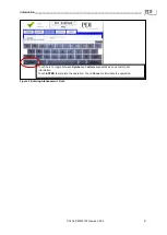
Страница 9: ...________________________ Ctrl Nr PM375103 Revision 003 9 Touch here to toggle between Symbol and Letters keyboards as you enter model information Touch ENTER to complete the operation Touch Cancel to terminate the operation Figure 3 Entering Alphanumeric Data ...

Страница 10: ... Connections The Color Monitor s backpanel has Modbus RTU and Ethernet ports Figure 4 For Color Monitors embedded in PDI products PDUs RPPs or JCOMMs Modbus RTU backpanel connections are typically made in manufacturing and extended to a terminal block or external panel for convenient customer access See 2 5 Customer Modbus RTU Connections The customer s Ethernet cable is connected directly to the ...

Страница 11: ...m Upstream and downstream chains can be differently configured For 2 wire configuration At least one device in a device chain must have both jumpers jumped on its Modbus connection If any device in the chain has jumpers installed for 2 wire all of the device chain is 2 wire To avoid confusion when troubleshooting all of the devices in the chain should be jumped in the same way TX or RX on the Moni...

Страница 12: ... and receive lines Therefore if the customer s Master device allows for control PDI recommends that the user turn on biasing and turn off termination which may fight the biasing Biasing the Master device s lines is not critical because the Color Monitor is already biasing the lines If termination is needed because of an extremely long cable run PDI recommends that a small capacitor be put in serie...

Страница 13: ... PDU s Contractor Board Basic and Enhanced Contractor Boards are shown Figures 6 7 Modbus RTU Upstream paralleled connectors Modbus RTU Downstream usually wired at factory Modbus RTU Upstream Connection Modbus RTU Downstream Connection to internal PDU devices usually wired at factory Figure 6 Modbus RTU Connections PDU Basic Contractor Board Figure 7 Modbus RTU Connections PDU Enhanced Contractor ...

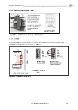
Страница 14: ...JCOMM Modbus Connections On PDI RPPs the Color Monitor upstream Modbus connection is brought to a terminal block for convenient customer connection Downstream connections are internal to the RPP and are wired at the factory Internal Label shows Modbus RTU wiring TX TX RX RX Common JCOMM Connections Panel Left Side of JCOMM Modbus Out Connector Modbus In Connector TX TX RX RX Common Modbus Plug Wir...

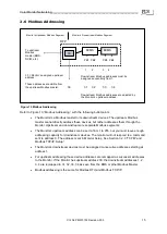
Страница 15: ... 2 3 TCP IP and Modbus TCP IP Setup The Monitor s downstream devices must be assigned consecutive addresses starting at address 1 For upstream addressing these device addresses are remapped as successor addresses to the Monitor If the Monitor has upstream address 30 the downstream addresses 1 2 3 4 are remapped to 31 32 33 34 as seen from the BMS or other Modbus Master Modbus addressing is the sam...

Страница 16: ...in system bring up that the registers you are addressing are the correct ones In a points list or Modbus register map the first analog channel is numbered 1 but is accessed in software with an index value of 0 Consequently it is common for a system to be one register off Because adjacent registers often have similar readings being one register off is not necessarily apparent Most analog values are...

Страница 17: ...s required to access and change setup parameters Enter the password default is PDI The user can navigate through any of the screens and come back to SETUP without having to re enter the password for 10 minutes Touch PASSWORD to change to a new password Touch buttons in the initial SETUP screen to link to miscellaneous setup functions PASSWORD Keyboard appears enter password then type new password ...

Страница 18: ... device name Unique device names are needed to isolate alarms and measurements to specific devices 3 2 2 Modbus RTU Setup Downstream Modbus settings cannot be changed Upstream Modbus provides network characteristics on the upstream side of the Monitor Address is the address that the upstream Modbus master such as the Building Management System BMS uses to address the Monitor The downstream device ...

Страница 19: ...s o Subnet Mask o Gateway Each connected monitor must be assigned a unique address DHCP is not supported Touch RESTART WITH NEW SETTINGS if any parameter is changed on this screen The processor will reboot and search the network for connections Figure 14 Modbus TCP IP and SNMP Setup 3 2 4 SNMP Setup To use SNMP the customer must connect an Ethernet link to the RJ45 header J11 see Figure 4 on the M...

Страница 20: ... customer specified model number for the unit in which the Monitor is installed such as a PDU or RPP The list has no configuration use it does not have parameters that determine Monitor operation MODEL number Touch MODEL and enter model number with the pop up keyboard On HOME screen touch the SOFTWARE VERSIONS button to display a scrollable list of versions levels for the Monitor and devices in it...

Страница 21: ...______________________________ Ctrl Nr PM375103 Revision 003 21 Display Version Number is given by the Monitor s onboard software Device Version Numbers are entered in device setup Go to DEVICES screen select device select VERSION field and enter data ...

Страница 22: ...t is identified by its Modbus slave ID and its own points list Modbus register map In the DEVICES screen device list the Monitor displays the devices it finds in order of discovery using these device types and default generic names 1 PDU Power Distribution Unit with PDU transformer measurements and contractor board alarms and relays 2 BCMS ESF BCMS Enhanced Subfeeds for large PDU subfeeds e g 250A...

Страница 23: ...onfiguration These settings provide information to the Monitor in addition to each device s own internal setup Device settings will usually be entered by PDI manufacturing or service representatives but can be entered by customer administrators 4 2 1 PDU Device Settings PDU devices Figure 17 have only two settings device NAME and VERSION Figure 17 Settings PDU Device Touch PDU generic name in devi...

Страница 24: ...p up keyboards You may have to enter a password first You can sequentially number panelboard circuits for up to eight 8 42 circuit panelboards allowing measurement and alarm identification for all 336 circuits in an 8 panelboard PDU Standard panelboards are always laid out 1 3 5 41 down the left side and 2 4 6 42 down the right side Select ODD EVEN to display them in this order or select STANDARD ...

Страница 25: ...mbering layout STANDARD Numbers increment in numerical order 1 2 3 42 down left side first 1 21 then right side 22 42 ODD EVEN List circuits as they are laid out on panelboard odd numbered circuits on left side even numbered circuits on right side such as 1 3 5 41 on left side and 2 4 6 42 on right side Touch to set VERSION number for BCMS software requires Version Number Update Password The new V...

Страница 26: ...try in the Monitor s device chain its own points list and its own Modbus address 4 2 5 BCMS IEC Settings IEC panelboards with up to 72 individual circuits use the BCMS IEC points list The initial generic device type is BCMS IEC Settings are only Device Name and Software Version Touch BCMS IEC device name in DEVICES list Device name turns blue when selected Available Settings Touch NAME box to brin...

Страница 27: ... the PDU transformer Figure 22 Select touch PDU device name in the device list Device name turns blue when selected and device name displays in header PDU is the default generic device name Users can change the device name in SETTINGS Touch READINGS to see PDU power monitoring data INPUT to the PDU transformer Voltage AB BC CA THD total harmonic distortion AB BC CA Frequency in Hz Current A B C op...

Страница 28: ...he device list PDU in this list Device name turns blue when selected and device name appears in header BCMS ESF is the default generic device name Users can change the device name in SETTINGS Touch READINGS to see the first screen of ESF power monitoring data NO Circuits are numbered 1 14 and broken out by phase 1A 1B 1C Instantaneous measurements AMPS KW KVA KVAR PF Power factor per phase Cumulat...

Страница 29: ...istering a current ACTIVE Current has read 0 after registering a current WARNING OK No warnings outstanding for this circuit ACTIVE warning outstanding ALARM OK No warnings outstanding for this circuit ACTIVE alarm outstanding NO Subfeed circuit by number and phase Instantaneous measurements by phase LOAD Load is a percent of the Full Load amperage for this breaker Full Load is a user specified pe...

Страница 30: ... different voltages Frequency Measurement in Hz Panelboard instantaneous readings Voltage AB BC etc to panelboard with THD Total Harmonic Distortion by phase Line 1 voltage source 1 Line 2 voltage source 2 if present Panelboard power measurements by phases ABC and total KW KVA KVAR PF Panelboard cumulative reading KWH panelboard total Clear Reset KWH to 0 Measurements and Alarms individual panelbo...

Страница 31: ...ircuit Figure 26 27 Select the device name The device name will highlight in blue Users can change the device name in SETTINGS Select READINGS to display panelboard power data Scroll among READINGS pages using PREVIOUS NEXT buttons Panelboard Circuits instantaneous Readings NO circuit number scroll through 42 circuits AMPS Amperes KW Kilowatts KVA kilovolt amperes KVAR kilovolt amperes reactive PF...

Страница 32: ...surements by phases ABC and total KW KVA KVAR PF Panelboard cumulative reading KWH to panelboard as whole Clear Reset KWH to 0 Panelboard totals instantaneous readings using main feed or BCMS computed measurements PB Amps Total panelboard measurements phases ABCNG Load Percent of maximum PB load as specified by user in points list Both PBs Sum of phase ABCN measurements for both panelboards not av...

Страница 33: ...s BCMS IEC panelboards have three readings screens Figure 29 For panelboard 1 individual circuits are numbered 1L1 to 1L72 Panelboard circuits are numbered sequentially down the left side 1L1 1L36 and then down the right side 1L37 1L72 BCMS IEC points list does not have the BCMS CB subfeeds option Touch BCMS Subfeeds generic device name in the device name list BCMS CB in this case Device name turn...

Страница 34: ...volt amperes reactive PF power factor KWH Kilowatt Hours Panelboard Circuits Measurements and Alarms NO Circuit Number AMPS Amperes CB Circuit breaker rating Amps MIN Lowest current read MAX Highest current read ZERO OK Current has not dropped to 0 since last reset ACTIVE Current has read 0 after having read a minimum current WARNING OK No warning outstanding ACTIVE warning outstanding ALARM OK No...

Страница 35: ...en touch the ALARM button to show the ALARM screen The ALARM Screen Figure 31 lists all outstanding warning and alarms by device name with a date time stamp in a scrollable list If no alarms are outstanding there will be only one line No Alarms The warning or alarm gives the device name and locates the device component that is the alarm source For example for a BCMS panelboard device the alarm may...

Страница 36: ... warning alarm will remain on the ALARM screen Device Name BCMS KW device generic panelboard device with KWH points list Device Name should be changed from generic name to user specified name on the device s SETTINGS screen Alarm or Warning Name Under Volt Main locates the problem to the main voltage source to the panelboard Step through the device s screen chain using NEXT to find the screen with...

Страница 37: ...te EPO on PDU can be activated in by closing the contacts on the contractor board When Remote EPO button is activated the alarm is activated and the unit s main input circuit breaker will then be shunt tripped off line Thermal Overtemp Stage 1 transformer temperature alarm 180 F or higher temperature registered in the transformer windings Thermal Hightemp Stage 2 PDU shutdown on transformer temper...

Страница 38: ...e B measures below threshold level optional Input Current C High Input current phase C measures above threshold level optional Input Current C Low Input current phase C measures below threshold level optional PDU Transformer Output Alarm Alarm Description NOTE If the PDU is configured for dual outputs Output 1 or Output 2 will prefix alarm instead of Output Output Voltage AB High Output voltage AB...

Страница 39: ... in points list Output KVA A High Output KVA phase A measures above preset level Output KVA B High Output KVA phase B measures above preset level Output KVA C High Output KVA phase C measures above preset level Output KVA Total High Output KVA Total measures above preset level Neutral Current High Neutral current measures above preset level Neutral Current Low Neutral current measures below preset...

Страница 40: ... A common circuit feeding both panelboards is over alarm threshold Under Curr both PBs A common circuit feeding both panelboards is under alarm threshold Over Volt Main Over voltage measured on main voltage source to panelboard Under Volt Main Under voltage measured on main voltage source to panelboard Over Volt Alt Over voltage measured on alternate voltage source to panelboard Under Volt Alt Und...

Страница 41: ...wnstream units Go to the Setup screen and press RESTART WITH NEW SETTINGS to force the display to search for downstream devices Monitor is in Active alarm state Red LED is solid and alarms are listed under Active alarms Go to the Alarms Screen and press CLEAR ALL It takes a few seconds to clear all alarms If the Alarms persist check the downstream device Monitor displays or 65536 The downstream de...

Страница 42: ...ges show a PDU with an M4G acquisition board M4GACK subfeeds monitored through the BCMS Enhanced Subfeeds points list and a Color Monitor Figure 34 Web Pages Device Chain Each web page has three buttons Click Home to return to Color Monitor Home page Click PDI to display the PDI web page Click Devices to display a list of all devices in the Color Monitor s downstream chain Figure 33 Web Pages Home...

Страница 43: ...ws the number of devices in the Monitor s device chain firmware level and a user defined model ID Figure 35 Figure 35 Web Pages Display Device The remaining devices have monitoring data Click the PDU device line brings up the PDU M4G acquisition board web page M4GACK Figure 36 Click Device 3 BCMS ESF in the Web Pages Device Chain Figure 37 to see monitoring data for the PDU s subfeeds to its downs...

Страница 44: ...stomer selected and connected to PDU Contractor Board All data and alarm values are mapped from the PDU M4G board points list See the points list for the PDU M4G board for more information No alarms for this device PDU board data is shown in series of tabbed screens Click tab to view screen Source 1 Input to PDU transformer Device type M4GACK PDU Acquisition Board Modbus address downstream from Mo...

Страница 45: ...t Device type BCMS ESF subfeeds group Modbus address downstream from Monitor 3 Device name BCMS ESF Subfeed data is shown in series of tabbed screens Click tab to view screen 70 Load is Warning level yellow 80 Load is Alarm level red Status Four 4 Digital Alarms NOTE These web pages present data from the device points list See the Enhanced Subfeeds points list for more information Figure 37 Web Pa...

Страница 46: ...ng and alarm thresholds KWH measurements are available at the panelboard level BCMS KWH Points list specialized for power measurement at the individual circuit level Warnings and alarms thresholds are set the same for all panelboard circuits BCMS ESF Enhanced Subfeeds Points list for large PDU subfeeds e g 250A BCMS CB Small points for measuring current in RPP subfeeds with CTs When used it has it...

Страница 47: ...IEC format panelboards with 36 or 72 1P circuits is 72 BCMSII plus points list Europe KWH For PDU points lists download the WaveStar PDU Customer CD a zip file Unzip the file and open the directory Points List for WaveStar PDU BCMS Version to find these points lists and use the latest revision given PDU board points list is M4G acquisition Points list Other points lists are the same as on the BCMS...

Страница 48: ...VAC or 30VDC The backpanel also has a RESET button If the Monitor hangs you can reset it by pressing this button Replaceable parts Fuse 200 mA 250V replace fuse with a UL recognized IEC compliant fuse of the same type Battery Lithium ion Panasonic BSG CR2477 3V 1 AH PDI Part Number 15174 Caution The battery used in this device may present a risk of fire or chemical burn hazard if mistreated Do not...

Страница 49: ..._______ Ctrl Nr PM375103 Revision 003 49 battery with Panasonic BSG CR2477 3V 1 AH PDI Part Number 15174 only Use of another battery may present a risk of fire or explosion Dispose of used battery promptly Keep away from children Do not disassemble and do not depose of in fire ...

Отзывы: