
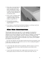
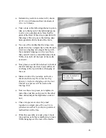


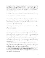


Make the pushrod from the supplied 4-40 materials, the solder clevis goes towards the
servo end after cutting the rod to length and the adjustable clevis attaches to the
control horn. Solder the clevis to the pushrod using a quality silver solder.
Repeat the installation of the servo, control horn, 4-40 pushrod and clevises for the
other flap.
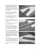
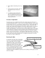
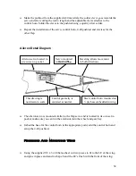
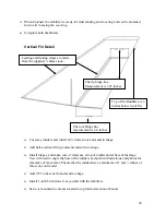
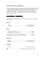
Aileron Detail Diagram
Aileron servo located in
pre cut servo pocket
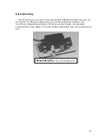
Servo mounted
in
Servo
Pro
Steel control horn mounted on
¼ ply base embedded in wing
Control geometry is
centered at neutral
This drawing is
not drawn to scale
Beveling allows movement
in both directions
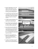
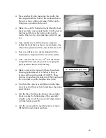
The aileron servo is mounted similar to the flap servo and is located in its own servo
pocket, make sure you can run the extension into the wheel and gear bay.
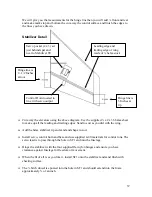
Imbed the base for the control horn at the appropriate point, add the control horn and
setup the 4-40 pushrod.
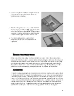
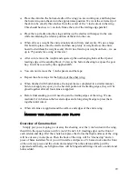
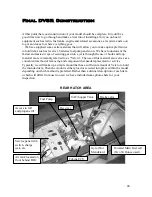
Finishing And Mounting Wing
Using the supplied 3/8 x 3 x 48 balsa sheet cut two pieces to fit to the LE of the wing
and glue in place and sand to shape. Sand the LE’s flush with the front of the wing.
34


