SERIES 8162 STRAIN GAGE SIGNAL CONDITIONER MANUAL
2
1.0
Description
Series 8162 Strain Gage Signal Conditioners provide
conditioned, amplified analog voltage and current
output for strain gage based sensors such as load cells
and reaction torque sensors. The units operate from
12 to 28 V
DC
power, and deliver ± 5 or ± 10 V and 4
to 20 mA output signals for recording, control, and
analysis purposes.
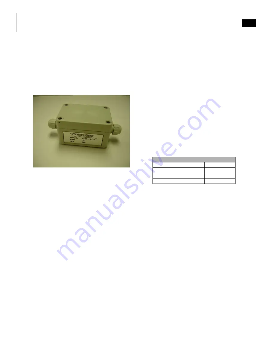
Figure 1 - Series 8162 Signal Conditioner
The Series 8162 Signal Conditioners provide a wide
strain gage input range from 0.5 to 11 mV/V, and are
housed in fire resistant, waterproof NEMA 4X (IP66)
enclosures. Standard features include an integral
shunt calibration switch with an internal resistor, a
two-pole active filter with 100 Hz cut-off, and
watertight compression fittings for easy installation.
Typically, Series 8162 Signal Conditioners are
configured to operate with a specific transducer
during system calibration at the factory. Therefore,
internal adjustments are not normally required prior
to initial use. However, should adjustments be
needed, the following sections outline instructions to
configure
the
conditioner
to
other
specific
applications.
2.0
Power Connection
The Series 8162 Signal Conditioner is designed to
operate on a customer supplied DC power source
with a voltage range of 12 to 28 volts. To connect
power to the conditioner,
a.
Loosen the four screws on top of the box and
remove the lid to expose the internal circuit
board.
b.
Insert a power cable through one of compression
fittings located on the side of the unit.
c.
Prepare the wire leads of the cable, then insert
the input voltage wire into the screw 1 position
on terminal J1. Reference Figure 4 for the J1
terminal location. Tighten the screw to fasten
the wire in place.
d.
Next, insert the Ground wire into the screw 2
position on terminal J1. Tighten the screw to
fasten the wire.
3.0
Transducer Cabling
High quality twisted pair shielded cable with four
conductors is recommended (such as Belden 8723)
for transducer hook up. PCB can supply finished
cables for transducers with either a PT02E-10-6P or
PC04E-10-6P receptacle if desired.
To connect the transducer to the conditioner, insert
the interconnect cable through a compression fitting,
then screw attach to terminal J2 per the arrangement
outlined in Table 1 below.
Table 1 – Transducer Cabling
+Signal (Green)
Screw 1
–Signal (White)
Screw 2
–Excitation (Black)
Screw 3
+Excitation (Red)
Screw 4
4.0
Analog Outputs
Two analog outputs are available on the 8162 Series
Signal Conditioner. The first is a voltage output that
is jumper selectable to either
±
5 or
±
10 volts. The
desired voltage output is set by the position of the P2
Jumper. Jumping pins 1 and 2 will set the
conditioner to
±
10 V
OUT
. Jumping pins 2 and 3 will
set the conditioner to
±
5 V
OUT
. Adjust Zero Balance
and Span by using the R23, R29, and R22
potentiometers on the conditioner’s internal circuit
board. Refer to Figure 4. Note that Zero Balance has
both a coarse and fine adjustment.
A 4 to 20 mA current output is the second available
output. The current output is adjusted using the R5
and R20 potentiometers. Reference Figure 4 for
exact locations of the potentiometers.
Connecting output instrumentation to the signal
conditioner is accomplished by attaching an
interconnect cable to terminal J3 on the conditioner’s
internal circuit board. Voltage output is fastened to
screw 4; current output is attached to screw 1.
Ground leads may be attached to either screw 2 or 3.
5.0
Transducer Excitation


