440 01 6101 00
77
Specifications subject to change without notice.
(clips) on blower wheel vanes. Do not bend wheel or blades
as balance will be affected.
7. If greasy residue is present on blower wheel, remove wheel
from the blower housing and wash it with an appropriate
degreaser. To remove wheel:
NOTE
: The DIBC composite wheel used in some models should
be cleaned with mild soapy water only. Allow wheel to dry prior to
reassembly.
a. Mark blower wheel location on shaft before disassembly
to ensure proper reassembly.
b. Loosen setscrew holding blower wheel on motor shaft.
NOTE:
Mark blower mounting arms and blower housing so each
arm is positioned at the same hole location during reassembly.
c. Mark blower wheel orientation and cutoff plate location to
ensure proper reassembly.
d. Remove screws securing cutoff plate and remove cutoff
plate from housing.
e. Remove bolts holding motor mounts to blower housing
and slide motor and mounts out of housing.
f. Remove blower wheel from housing.
g. Clean wheel per instructions on degreaser cleaner. Do not
get degreaser in motor.
8. Reassemble motor and blower wheel by reversing items 7b
through 7f. Ensure wheel is positioned for proper rotation.
9. Torque motor mounting bolts to 40 +/-- 10 lb--in. when re-
assembling.
NOTE
: Ensure that the removable inlet ring is installed before the
motor on furnaces with a DIBC composite blower.
10. Torque blower wheel set screw to 160 +/-- 20 lb--in. when
reassembling.
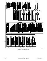
SET SCREW
MOTOR WHEEL HUB
MOTOR SHAFT FLAT
SCREW
MOTOR ARM
GROMMET
SCREW LOCATION
BLOWER HSG ASSY
BRACKET
BRACKET
ENGAGEMENT
SEE DETAIL
A
CAPACITOR
OR POWER CHOKE
(WHEN USED)
BRACKET
SCREW
(GND)
BLOWER HSG ASSY
MOTOR, BLOWER
WHEEL, BLOWER
CUTOFF, BLOWER
DETAIL
A
Representative drawing only, some models may vary in appearance.
A11584
Representative drawing of DIBC blower wheel only,
some models may vary in appearance.
A190094
Fig. 63 -- Blower Assembly
11. Verify that blower wheel is centered in blower housing and
set screw contacts the flat portion of the motor shaft. Loosen
set screw on blower wheel and reposition if necessary.
12. Spin the blower wheel by hand to verify that the wheel does
not rub on the housing.
13. Reinstall blower assembly in furnace.
14. Reinstall 2 screws securing blower assembly to blower
deck.
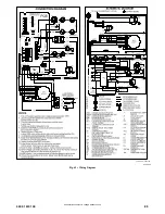
15. Reconnect blower leads to furnace control. Refer to furnace
wiring diagram, and connect thermostat leads if previously
disconnected.
NOTE:
Be sure to attach ground wire and reconnect blower
harness plugs to blower motor.
ELECTRICAL OPERATION HAZARD
Failure to follow this warning could result in personal injury
or death.
Blower door switch opens 115--v power to control. No
component operation can occur unless switch is closed.
Caution must be taken when manually closing this switch for
service purposes.
!
WARNING
16. Downflow or horizontal furnaces with vent pipe through
furnace only:
a. Install and connect short piece of vent pipe inside furnace
to existing vent.
b. Connect vent connector to vent elbow.
17. Turn on electrical supply. Manually close blower door
switch. Use a piece of tape to hold switch closed. Check for


