Users Manual Model 676
Control Panel Operation
•
29
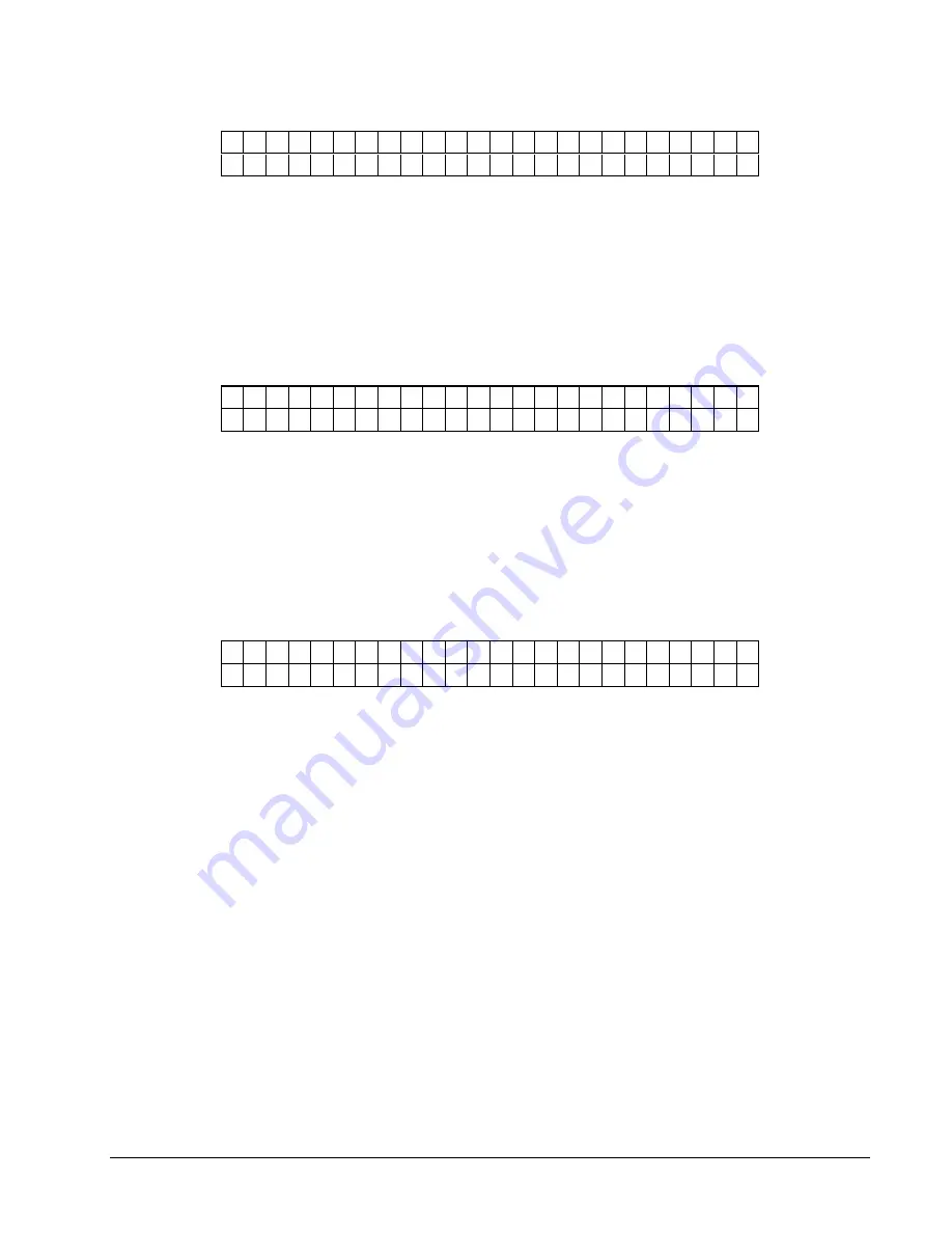
H E A D
C A T E G O R Y
S T A T I O N
2
V A L U E : ± X X
N E W
V A L U E : ± Y Y
This screen follows HEAD CATEGORY STATION 1. The screen allows the user
to enter the head category for station 2. The <YES / NO> buttons are used to change
the head category value. The value ranges from 1 to 8. Pressing ENTER will
change the head category value to the new value. See the section “PRINTHEAD
REPLACEMENT” for instructions on setting the head category.
Pressing the MODE/Down Arrow key will take the user to the next screen.
Pressing the EXIT/Up Arrow key will take the user back to the HOME screen.
H E A D
C A T E G O R Y
S T A T I O N
3
V A L U E : ± X X
N E W
V A L U E : ± Y Y
This screen follows HEAD CATEGORY STATION 2. The screen allows the user
to enter the head category for station 3. The <YES / NO> buttons are used to change
the head category value. The value ranges from 1 to 8. Pressing ENTER will
change the head category value to the new value. See the section “PRINTHEAD
REPLACEMENT” for instructions on setting the head category.
Pressing the MODE/Down Arrow key will take the user to the next screen.
Pressing the EXIT/Up Arrow key will take the user back to the HOME screen.
S T A T I O N
A C T I V A T I O N
1 2 3
C L O S E
H E A D S
P R E S S
E N T E R
This screen follows HEAD CATEGORY STATION3. The screen allows the user to
configure the printer for the number of heads in the system. The numbers ‘1’,’2’,’3’
stand for stations 1, 2, and 3. If the number appears on the screen then it means that
station is activated. If the number doesn’t appear on the screen then that station is
not activated and the printer will not print, look for ink out, or look for head open on
that print station.
The printer determines if a head is in the system by checking the head open switch
when the ‘Enter’ button is pressed. If the user would like to disable a station that is
in the machine for reasons of convenience then they can just open the head for that
station and press enter.
If the operating system has been changed or TCBSETUP has been used to re-
initialize the machine it will show all print stations active as the default. If it is a 1/1
printer that doesn’t have station 3 installed then the user will have to come to this
screen and press ‘Enter’ to deactivate station 3, otherwise the printer will show INK
OUT STATION3 errors when it is run.
Pressing the MODE/Down Arrow key will take the user to the first screen under
PRINTHEAD SETUP.
Pressing the EXIT/Up Arrow key will take the user back to the HOME screen.
Содержание 676
Страница 2: ...Users Manual Model 676 This page intentionally blank ...
Страница 85: ...Users Manual Model 676 Mechanical Assembly Drawings 85 Mechanical Assembly Drawings ...
Страница 86: ...86 Mechanical Assembly Drawings Users Manual Model 676 Unwind Assembly Drawing ...
Страница 88: ...88 Mechanical Assembly Drawings Users Manual Model 676 Web Guide Light Bar Assembly Drawing ...
Страница 92: ...92 Mechanical Assembly Drawings Users Manual Model 676 Top Printhead Assembly Drawing ...
Страница 94: ...94 Mechanical Assembly Drawings Users Manual Model 676 Ink Save Printhead Assembly Drawing ...
Страница 96: ...96 Mechanical Assembly Drawings Users Manual Model 676 Bottom Printhead Assembly Drawing ...
Страница 98: ...98 Mechanical Assembly Drawings Users Manual Model 676 Ink Unwind Assembly Drawing ...
Страница 100: ...100 Mechanical Assembly Drawings Users Manual Model 676 Ink Rewind Assembly Drawing ...
Страница 102: ...102 Mechanical Assembly Drawings Users Manual Model 676 Ink Rewind w Head Lift Assembly Drawing ...
Страница 104: ...104 Mechanical Assembly Drawings Users Manual Model 676 Ink Rewind Station 3 1 over 1 Assembly Drawing ...
Страница 108: ...108 Mechanical Assembly Drawings Users Manual Model 676 Stacker Assembly Drawing Part 1 ...
Страница 110: ...110 Mechanical Assembly Drawings Users Manual Model 676 Stacker Assembly Drawing Part 2 ...
Страница 112: ...112 Mechanical Assembly Drawings Users Manual Model 676 Rewind Assembly Drawing ...
Страница 114: ......
Страница 116: ...116 Mechanical Assembly Drawings Users Manual Model 676 Optional 4 1 4 Pick up Assembly ...
Страница 118: ...118 Mechanical Assembly Drawings Users Manual Model 676 Optional 4 1 4 Stacker Assembly ...
Страница 122: ...122 Mechanical Assembly Drawings Users Manual Model 676 Drive Belt Routing 1 over 1 Drawing 3 9 7 7 1 5 4 2 5 4 8 4 7 6 ...


