


Configuring the security interfaces
71
Models 2603, 2621, & 2635 High Speed Routers User Guide
5 • Security
The next step in configuring the router is adding the default gateway route. Since the WAN IP address of the
IPLink router modem at the CO site is 192.168.101.2, this will be the gateway for the IPLink router modem
at the CPE site, the modem we are currently configuring.
1. Click on
IP Routes
under Configuration on the IPLink router modem’s Menu.
2. Click on
Create a New IP Route
.
3. Enter 192.168.101.2 in the box adjacent to Gateway.
4. Leave Destination and Netmask both as 0.0.0.0 because this is the gateway default route.
5. Click on
Create
and the route will be entered.
6. The default gateway can be verified by clicking on
IP Routes
under Status in the menu.
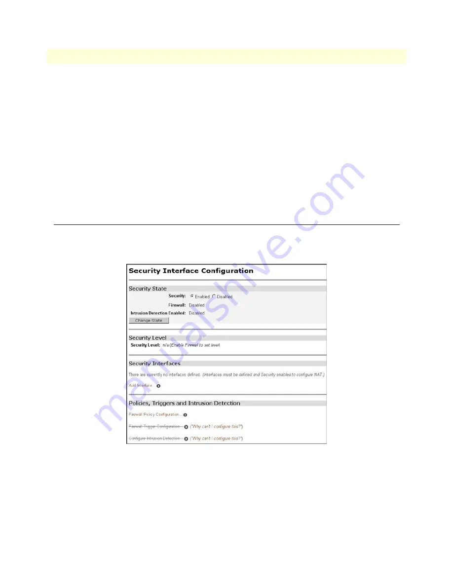
Configuring the security interfaces
The interfaces and routes have been configured on the IPLink Router which will function as the firewall. The
Ethernet side of the IPLink router will be configured to be an internal security interface whereas the WAN side
is configured as an external security interface since it is on “public” side of the modem connection.
1. Click on
Security
under Configuration on the IPLink router modem’s menu.
2. Under Security Interfaces, click on
Add Interface
.
3. Select Name of the WAN port (PPPoH) and Interface Type to be external. Click on
Apply
.
Содержание IPLink 2603 Series
Страница 8: ...Contents Models 2603 2621 2635 High Speed Routers User Guide 8 ...
Страница 14: ...About this guide Models 2603 2621 2635 High Speed Routers User Guide 14 ...
Страница 23: ...23 Chapter 2 Product Overview Chapter contents Introduction 24 Applications Overview 25 ...
Страница 26: ...2 Product Overview Models 2603 2621 2635 High Speed Routers User Guide 26 Applications Overview ...
Страница 40: ...3 Quick Start Installation Models 2603 2621 2635 High Speed Routers User Guide 40 Hardware installation ...
Страница 78: ...5 Security Models 2603 2621 2635 High Speed Routers User Guide 78 Intrusion Detection System IDS ...
Страница 89: ...89 Chapter 8 Monitoring Status Chapter contents Status LEDs 90 ...
Страница 98: ...9 T1 E1 Diagnostics Models 2603 2621 2635 High Speed Routers User Guide 98 Software Upgrades ...
Страница 108: ...A Specifications Models 2603 2621 2635 High Speed Routers User Guide 108 Power and Power Supply Specifications ...
Страница 109: ...109 Appendix B Cable Recommendations Chapter contents Ethernet Cable 110 Adapter 110 ...
Страница 114: ...C Physical Connectors Models 2603 2621 2635 High Speed Routers User Guide 114 Serial port E1 T1 RJ 48C Connector ...


